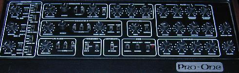
This is a collection of my circuit modifications and some other miscellaneous
information about the Sequential Circuits Pro-One synthesizer.
This was originally posted to the analogue heaven email list.
- G. Forrest Cook (1997)
Pro-One hum fix:
I discovered a bad hum problem in a Sequential Circuits Pro-One synthesizer,
Rev 1.2. I tracked the problem down to a dreaded "Ground Loop", this one
was even factory installed. The power transformer's center tap was grounded
at the case, which connects to the power cord (AC) ground. The power
supply ground formed a ground loop that went out of the the power
line ground, in to the amplifier's power ground, and back to the Pro1
via the output jack. Some of the transformer's AC output followed this
path and would cause an AC ground current to travel through the audio shield,
which was added to the audio signal, can you say HUM? Sure you can.
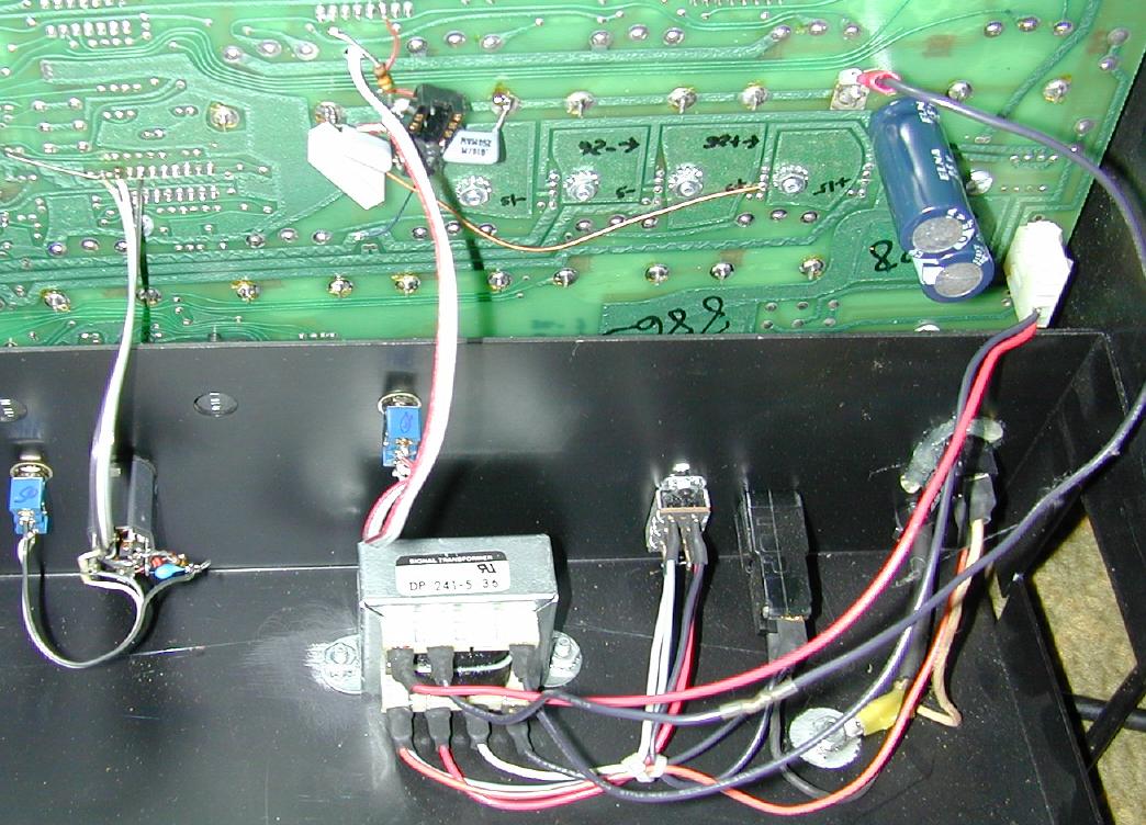
The fix: move the transformer's center tap wire to a ground point on the
main circuit board. This disconnects the transformer's secondary circuit
from ground. Now, the only ground path to the low voltage side of the
transformer is via the output jack. The center tap wire is the only
transformer wire that goes to ground. Lengthen the center tap wire with
another piece of wire. Connect the longer wire to the printed circuit ground
near the two 1000 uF filter caps that stick out of the back of the board.
The large metal surface on the board is the ground. There are some
potentiometer mounting tabs near the caps that are fairly stout places to
solder. Completely remove the black wire that goes from the output jack
to the chassis, that's the "loop" in the ground loop. Voila, hum gone.
Some concerns: Definitely leave the green power cord wire connected to the
frame, that's for yer safety. Be very careful to connect the center tap to
a ground, not all of the big metal surfaces on the PC board are ground, ohm it
out if you're unsure. Be sure to unplug the Pro-1 before performing any work.
Pro-One envelope mod (WITH SCHEMATIC):
Ok, there's been enough interest in the envelope inverter mods to the
Sequential Circuits Pro-One that I'll post the circuit.
First off, you should have SOME experience working with a
soldering iron and circuit boards before attempting this.
The results are that you can almost double the repertoir of sounds
available on the synth.
Here's how you perform the modification:
1: unplug the unit.
2: remove the screws that hold the top and bottom together.
3: remove all of the knobs.
3: At this point you should start observing standard static procedures,
ground your hands to the chassis before touching the innards of the PC
board and refrain from shuffling across wool rugs before touching the
board.
4: remove the circuit board from the top of the case.
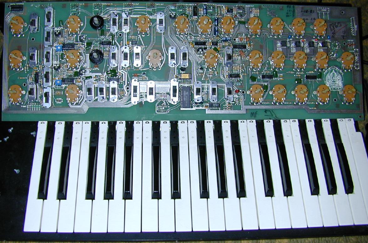
5: Locate U116, one of the Curtis 3310 envelope generator ICs that has
lots of traces running to the envelope ADSR potentiometers. On the
top of the board there is a 24K resistor going from U116 pin 10 to
U116 pin 2. Leave this connection but follow the trace on the pin 2
side, the line runs off to the "envelope amount" pot, cut this trace.
Call the U110 pin side of the cut "f-env" and the other side "f-mod"
6: Build a standard circuit for an inverting amp, gain of 1 with a 741
Op-Amp as follows: input: 10K resistor connects to 741 pin 2.
Feedback: 10K resistor connects from pin 2 (-) to pin 6 which is the output.
Bias: connect a 4.7K resistor from pin 3 (+) to the center tap of a
10K trimmer pot, 10 turn type is best. Connect one side of the trimmer
to ground and the other side to the +15 Volt bus.
7: Wire the 741 power: pin 4 goes to -15V and pin 7 goes to +15V. I put a
0.01 uF cap from pin 4 to ground and pin 7 to ground for supply bypass.
8: Mount a single pole double throw switch wherever you can, I put mine
on the back panel between the cutoff and resonance knobs. Top mounting
would be a bit easier to use but I wanted to retain the original appearance.
9: Connect the free end of the input 10K resistor to U116 pin 2.
10:connect the center of the SPDT switch to the "f-mod" line.
11:connect one end of the SPDT switch to the "f-env" line.
12:connect the other end of the SPDT switch to the inverter output, 741 pin 6.
13:double check your wiring, look for solder bridges and loose bits of solder.
14:reassemble the unit.
15:adjust the bias trimmer for best response. This is a subjective adjustment.
I set up a good sounding non-inverted envelope with the filter cutoff
around 5, flipped the invert switch, and adjusted the trimmer while
playing until I got a reasonable sound. Play with it.
Hints: I suggest using the shortest wires possible, my construction involved
putting the 8 pin 741 IC into a 14 pin wire-wrap socket and soldering
two of the unused pins of the socket to a big ground plane on the back
of the board for a stable mounting point. I soldered the resistors onto
the socket before mounting the socket. I drilled a hole near the cut
trace in step 5 to run the f-mod and f-env signals to the inverter.
Make sure you don't hit a trace on the other side of the board.
The ground line is easy to find, all of the envelope pots have their
metal cases soldered to it. To find the + and - 15V lines, carefully
measure the voltages on the board near the power supply regulator section,
look for the heat sinks until you find + and - 15V relative to ground.
If that doesn't make sense to you, try tapping off of a known IC's supply
pins, TL082 chips have -15 on pin 4 and +15 on pin 8.
Parts are available from any reputable electronics store and Ratty-ol'-Hack
stores as well.
That's it, be careful, don't fry anything (including yourself).
Nyooooweet Nyooooweet Nyoooweet...
f-env --------------------------------
| 10K |
| --/\/\/\-- | Normal
| | | ----O
+15V | | +15V | -----0---- f-mod
| | 10K | 2|\| | ----O
/ |-/\/\/\----|---|-\7 | | Invert
\ 3| \6_|____|
/<--------/\/\/\--------|+ /
\ 4.7K 741 | /4
/ |/|
| -15V
Ground
Pro-One insert mod:
Well, all of this talk about inserting effects into synths got me going
AGAIN. This list sure is great for inspiring ideas. I put an insert
jack in between the oscillators and the VCF/VCA on my trusty Pro-One.
The back panel is starting to resemble shotgunned swiss cheese.
(2 holes actually). The mod was trivial and the results are very
interesting. I have only tried a phaser pedal which didn't like the
levels and a fuzz box which sounded great. I still need to insert a digital
reverb in the chain. The fuzz gives a really nice metallic sound when using
the two oscillators, it sounds a bit like a smoothed out ring modulator.
This mod is definitely good for fattening up the sound of the synth.
I'm beginning to sound like a stereo salesman, say "delicate nuances"...
The mod consists of cutting the line (lines actually) that go from the
oscillators and noise source to the Curtis 3320 VCF chip, pin 1. Leave
the resistor that goes from pin 1 to pin 7 in place. I installed 3 wires
from the board to the back of the unit, ground, send (from oscillators) and
receive (to 3320 pin 1). The insert jack I used is a 1/4" stereo jack with
switching on both tip and ring. The tip and ring SWITCH contacts are wired
together so the signal can go straight through the jack when nothing is
plugged in. The send line went to TIP and the receive comes from RING.
That's how my Seck board is wired, so I adhered to their standard. The
ground line goes to the SLEEVE contact (outside shell) of the jack.
IMPORTANT: either use a plastic insulated jack or get some of those
fiber washers with collars (or drill a big hole and mount a piece of plastic
in it to hold the jack, DON'T ground the insert jack to the chassis or
you will re-introduce the above mentioned ground loop and get HUMMMM.
This is fairly tricky surgery, Don't attempt this unless you have some
experience working on PC boards and dealing with sensitive electronics.
Insert circuit schematic and modification:
After playing a bit with my Pro-One insert circuit mod I discovered that
the filter stage was being overdriven and needed a better ground reference
as well as DC isolation from the effects boxes. The following circuit
takes care of all of these problems.
Unfortunately, I had to add another switch, but that's not all bad since
it gives you the option of removing the insert without pulling jacks.
Board Ground
| Stereo Phone Jack (effect insert)
sleeve ----=== 50K Aud Pot (return level)
ring <---------/\/\/\/---------------+---Ground
tip > ^ |
|- | |
- 10uF | |
- | |
|+ | 100K |
O | --/\/\/\/--|
From Osc. O----- | - + |
O ---| |--+------O
| 10uF -----O To Filter Input (3320-1)
-----------------------------O
Note: the two switches are parts of one DPDT switch.
Up is for insert, down is for bypass (normal)
The 10uF caps shown are electrolytics, non-polarized caps would be preferable.
Pro-One trivia from the analogue heaven list:
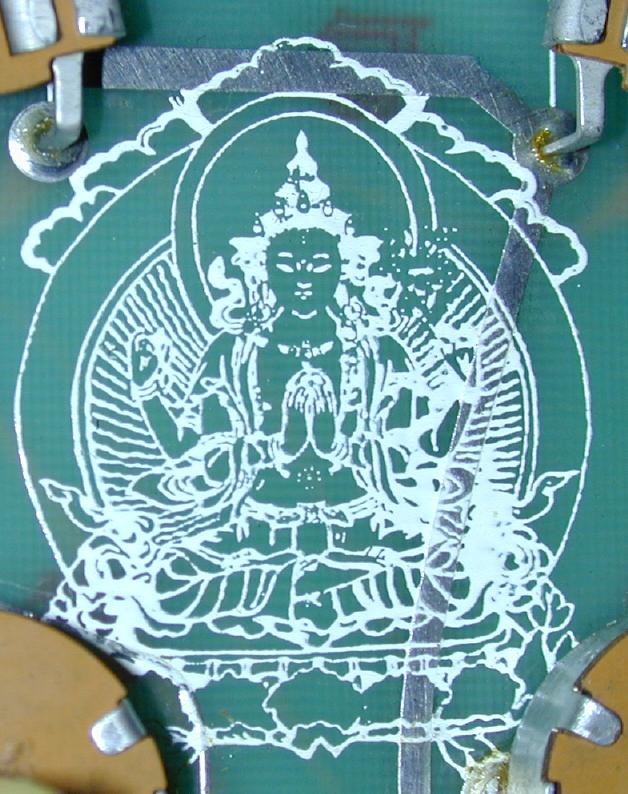
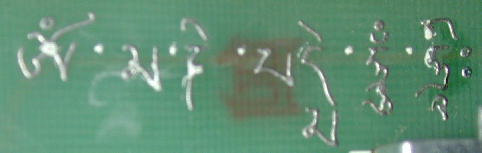
> > Speaking of the Pro-One, I noticed the circuit board had some interesting
> > things on it such as a silkscreened Buddah, some metal 'shrooms and flowers,
> > and a bunch of Sanskrit? writing. Anybody know the story behind that?
>
> A friend of mine who has one bought his new. It went bad one day, so he
> opened it up and there was a silkscreen of Shiva on the board (Maybe it
> was Buddah, I don't think he's an expert on Eastern mythology). He sent
> it in to be serviced and they (SCI) replaced the whole board. No more
> Buddah! )-;
the 6trak has a mandala (sic) on its board.. and the original code was
written so that it would include the mantra chant... so, each time we
turn on our six traks, that buddist programmer becomes PURER AND PURER!
heheheheheh (smj@sdf.lonestar.org (Stephen M. Jones))
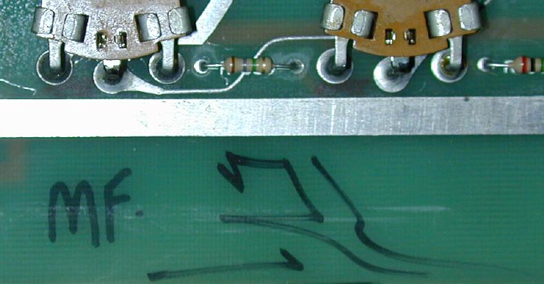
Chet Wood, an earlier programmer etc. at Sequential (also worked for
Terry Riley), often ASCII-encoded mantras in the code; various weird
things also appeared on the silkscreen of the circuit boards (such as
the banana slug under the 68000 in the Studio 440 - guilty). Then there
was the garlic mod to early P-5s that a San Mateo shop would do, which
consisted of a clove of garlic glued to a chip shoved in an unused socket...
(Chris Meyer )
Check out my Analogue Heaven page.
This page is a small part of SolOrb