(C) 1997 G. Forrest Cook
This circuit is a generic low power temperature controller that can be used for stabilizing temperature sensitive electronic circuits. It was built to stabilize a radio frequency VFO (Variable Frequency Oscillator) for ham radio applications. The circuit has also been used to lower the drift of a Ramsey FM10a micropower FM transmitter.
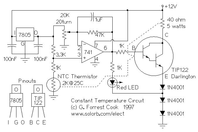
The 7805 voltage regulator provides a reference voltage that is fed into a resistive bridge formed on one side by the 20K trimmer and the other side by the 3.3K resistor and the 1K/thermistor combination. The termistor is an NTC (Negative Temperature Coefficient) type. The op-amp is run in a differential mode and tries to keep its inputs at the same potential via the thermal feedback loop formed between the heater and the thermistor.
The three 1N4001 diodes are used to bias the emitter of the transistor up enough that it can shut off fully with the limited voltage swing from the 741 op-amp. The heating indicator LED also taps off of the same diode ladder to enable the LED to shut off entirely.
The value of the capacitor in the op-amp feedback loop (1uF) may need to be adjusted if the circuit "rings", or swings back and forth before stabilizing on a temperature. The capacitor value is specific to the thermal mass that is being temperature-stabilized.
The heater resistor is rated at approximately 40 ohms and 5 watts. The value of the resistor determines the heating rate and the power consumption. The resistor value should not be too low or the resulting high current will damage the 1N4001 diodes and/or the TIP122 transistor.
The original version of this circuit was built on a perforated circuit board using point-to-point wiring. The circuit could also be built on a printed circuit board. The thermistor and most of the heat generating components (the 40 ohm resistor and the 3 1N4001 diodes) were epoxied to an L-shaped aluminum bar, the rest of the components were mounted on the perforated circuit board. The circuit board was then mounted on the aluminum piece with insulating standoffs.
The TIP122 transistor can also be mounted to the aluminum bar. The mounting tab of the TIP122 is electrically hot, it should be isolated from the aluminum bar with an insulating washer. An alternate construction method would be to mount the transistor on its own electrically isolated heat sink. Use heat conducting grease when mounting the transistor. Be sure that the thermistor has a good thermal contact with the 40 ohm resistor. The 78L05 regulator's mounting tab does not require a heat sink, it should be electrically isolated from the TIP122 tab.
The 40 ohm resistor and TIP122 heat sink should be mounted near the item that is to be temperature controlled. I recommend forming a box out of styrofoam insulation that surrounds the temperature regulator and the temperature controlled device. The insulated box will reduce power consumption, speed up the initial warm up period, and isolate the internal components from external temperature changes.
Adjust the 20K pot to the center of its range and power up the circuit. The LED should start out bright, then gradually dim down as the circuit reaches equillibrium. Put a thermometer or temperature probe on the 40 ohm resistor and measure the temperature. Adjust the 20K pot until the resistor reaches the temperature that you desire.
If the circuit is properly damped, it should not oscillate on the initial warm-up. The voltage on the 741 op-amp output (pin 6) can be monitored with a volt meter to observe the circuit's operation. If the pin 6 voltage oscillates slowly at startup, you may need to increase the value of the 1uF feedback loop capacitor. Be sure to use a non-polarized capacitor, not an electrolytic type.
Operating Voltage: 10-15 Volts DC
Operating Current: 250mA at 12 Volts DC input initial current
Apply power to the circuit, let all of the components warm up. The heating resistor will stabilize to a constant temperature.
Back to FC's Electronic Circuits page.