(C) 2005, G. Forrest Cook
The CARL device is an add-on numerical counter that plugs into the headphone jack of 1960s vintage geiger counters such as the Victoreen CDV700 and CDV700-6B. It should also work with the Lionel ENI/LENi counters, and any other geiger counter that has a headphone output pulse greater than -5V.
Vintage 1960s era geiger counters don't actually count, they use an analog meter with an integrator circuit to give short-term averaged readings of radiation detections (clicks). The CARL circuit keeps track of the total number of clicks for a period of either 60 or 600 seconds (1 or 10 minutes). This provides a way to get a long-running count of low-level radiation from sources such as radon gas, rock samples and background radiation. The CARL circuit allows for the measurement and comparison of radioactive sources that are of levels that don't produce measurable readings on analog geiger counter meters.
In my Colorado location, the CARL counter shows background radiation levels of 15-20 clicks per minute upstairs and 20-25 clicks per minute in basements where radon gas is present.
As a collector of rocks, my interest in making this device was to find all of the radioactive minerals in my collection, and remove them from my living space. I found quite a few rocks that registered above the background level, fortunately, I did not find anything super-hot. I have also used the meter to compare background levels in various geographical locations.
Operating Voltage: 5.7V DC nom
Operating Current: 16ma light off, 36ma light on
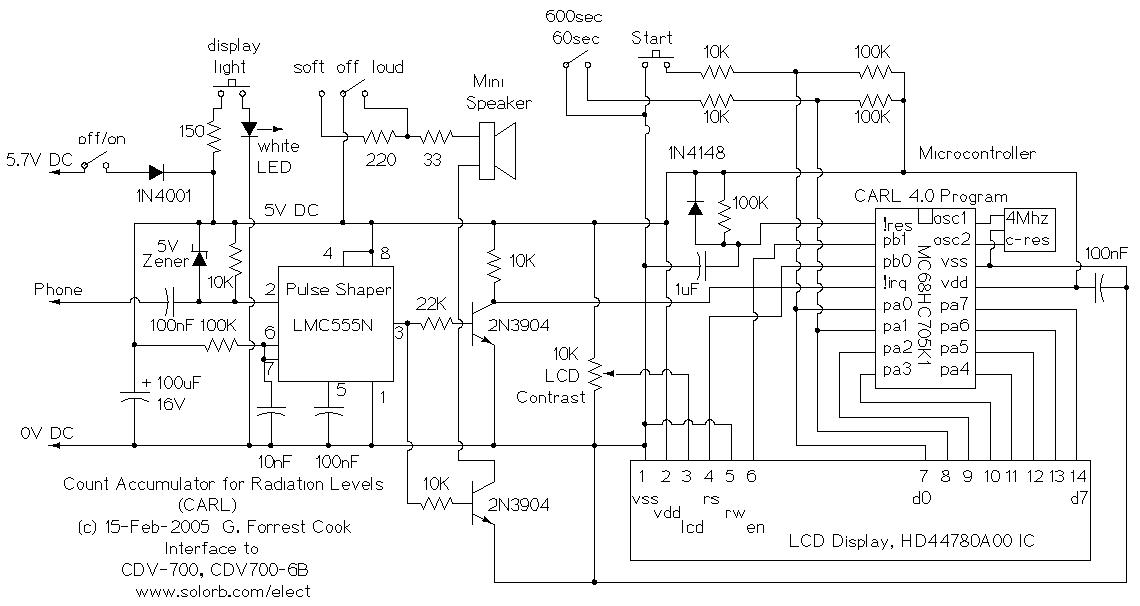
The main parts of the CARL circuit include an input pulse shaper, an audio click sounder, a microcontroller that runs the counter program, and a liquid crystal display module (LCD).
DC power at approximately 5.7V is used to power the circuit. The 1N4001 diode drops that to around 5V. The 5.7V shown on the schematic comes from the low voltage dropout regulator circuit in the companion "Hot Rod CDV700" modification circuitry. The microcontroller and LCD module are capable of operating anyhere in the 3-6V range, 5 Volts is optimal.
The CDV700 geiger counter produces a negative going pulse on the phone output with about a -20V swing. The pulse is limited to -5V by the 5V zener diode, then fed into the LMC555N CMOS timer IC, which lengthens and squares the pulse. The pulse width is around 1.5 milliseconds. The zener diode limiter prevents the negative-going headphone signal from going below 0V (5V less than +5V), this prevents the CMOS timer input from latching up or being damaged.
The pulse output on pin 3 of the 555 is inverted by the upper 2N3904 transistor to create a low-active pulse, that signal goes to the microcontroller interrupt pin for counting purposes. The pulse is also inverted by the lower 2N3904 transistor, that signal is used to drive the mini speaker which produces a clicking sound when the Geiger-Mueller tube fires. The soft/off/loud SPDT center-off volume switch selects either a 220 or 33 ohm series resistor or disconnects the speaker for silent operation.
One could easily extend the interrupt pulse signal to a ttl-compatible input on an external computer. It should be possible to feed the signal to an input on a PC parallel port, for example. The pulse could also be used to drive a simple TTL or CMOS counter circuit.
The diode, resistor, and capacitor on the microcontroller reset pin is used to delay the program startup and provide a clean reset operation. This is required so that the LCD module can get up to speed before the microcontroller starts. The microcontroller's main clock comes from the 4 Mhz ceramic resonator. The LCD gets data from the microcontroller's port A0-7 pins. The port B0 and B1 pins from the microcontroller drive the rs (data/control) pin and the en (enable-strobe) pin on the LCD. Ports PA0 and PA1 serve double duty, when the microcontroller is not using them to output data to the LCD, they are used as inputs to monitor the start and 60/600 second switches.
The 10K pot is used to set the LCD contrast, this is for adjusting the optimum viewing angle. The display light switch activates the white LED through the 150 ohm current limit resistor. This allows the display to be read in low light conditions.
Different LCD configurations can be used in this circuit as long as the LCD uses the common Hitachi HD44780ADO controller IC, or an equivalent JRC brand controller. I have built two versions of this circuit, one with a 2X8 LCD and another with a 1X16 LCD. The assembly language code has constants defined for placing the location of the time countdown, the radiation counter, and the Run/Stop indicator at particular LCD locations.
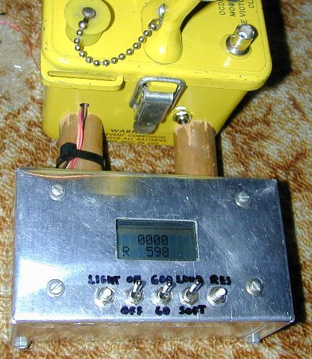
The CARL circuit was hand-wired on a small piece of perforated board. The perforated board was mounted on the back of the LCD display using four 4-40 screws and 1/4" nylon spacers. The board/LCD assembly was mounted inside of an aluminum box. The aluminum box had holes cut in the front for the switches and LCD display, and holes for the speaker and wires to the geiger counter.
A 1/8" sound hole was drilled in the side of the box and the mini-speaker was mounted behind the hole with epoxy glue.
The CARL box was connected to the back of the geiger counter using two 1-3/4" long wooden dowels. The dowels were drilled down the center and a pair of 2" 6-32 machine screws secure the box to the counter. The dowel length was chosen to allow the counter's cover latch mechanism to continue to function. A set of small holes were drilled in the side of the two boxes for the wires to pass through, a wire tie secures the wires to the dowel.
Operation starts with placing the geiger probe near the object you are measuring. For best accuracy, do not move the probe during the reading. Select 60 or 600 seconds with the 60/600 switch, press reset (labeled "start" on the schematic), and wait for the timer on the lower display line to count down to 0 seconds. The character on the lower left part of the display will be "R" for Run, when the counter is counting down, or "S" for Stop when the counting has ended. At zero seconds, read the accumulated count from the upper line of the display.
It is a good idea to measure the background radiation levels before measuring a suspect item. If the background beta+gamma level reads 150 counts in 10 minutes, then you know that a rock that measures 300 counts is somewhat "warm". If you get readings in the thousands/minute or higher, you might want to leave the area.
If you want to inventory a collection of items, for example a rock or pottery collection, write down the count levels for beta+gamma (shield open) and gamma only (shield closed) on a piece of paper, or pencil the values on the bottom of the item.
The soft/off/loud switch controls the click volume from the miniature speaker. The display light switch turns on a white LED that is mounted near the LCD for reading in low light conditions.
Keep in mind that gamma radiation only travels through a few inches of air, gamma readings should be taken with the probe adjacent to the measured material.
If you want to measure a fairly radioactive substance, such as the test source on the side of the geiger counter, it may be necessary to take a shorter reading and multiply the answer. For example, take a 10 second reading and multiply by 6 to get clicks per minute, or take a 30 second reading and multiply by 2. The longer you sample, the better the statistical average will be.
My advice for handling low-level radioactive rocks is to do so briefly, use gloves if possible, and wash any residual dust from your hands quickly. Don't create dust or breathe in any dust. The harmful effects of exposure to radioactivity is cumulative over time. You may receive a few extra clicks from handling a hot rock, but if you sleep with it under your pillow, you will get a large number of clicks. Don't do that. Also, low-level background radiation happens everywhere all of the time, and it has always been that way.
I am not a nuclear scientist, but I can safely state that one should never handle high level radioactive materials without proper equipment, knowledge, and presumably, government clearence.
A note on calibration: The number of ticks the counter measures from a given radioactive source depends on the condition of the geiger tube, the ambient temperature, the area of the tube that is exposed to the radioactive source, the voltage on the tube, and other factors. The counter should be calibrated relative to a known source or other calibrated meter. It is possible to use a given counter to compare relative readings, assuming the temperature and battery voltage are relatively constant. The voltage regulator modification described in the companion article will help to eliminate the variable of battery voltage changes.
The CARL 4.0 Assembly Language Program needs to be assembled, the resulting binary file should be used to burn an MC68HC705K1CP microcontroller chip. I used a Motorola KICS system running on an old DOS computer to do the programming. The software is highly optimized, some code inlining (removal of loops and subroutines) was performed to minimize stack usage. There are only a few unused bytes of RAM and ROM in the microcontroller, the program is somewhat of a "tight fit" for this particular chip.
1X Motorola MC68HC705K1CP microcontroller programmed with CARL4.asm software
1X 4.0 Mhz ceramic resonator, 3 pin
1X 7555 CMOS 555 timer chip
2X 2N3904 NPN transistor
1X 1N4001 diode
1X 5V 500ma zener diode
1X 1N4148 signal diode
1X white (or other color) LED
1X 100uF 16V electrolytic capacitor
1X 1uF capacitor
3X 100nF capacitor
1X 10nF capacitor
1X 10K trimmer potentiometer
1X 33 ohm 1/4W resistor
1X 150 ohm 1/4W resistor
1X 220 ohm 1/4W resistor
5X 10K ohm 1/4W resistor
1X 22K ohm 1/4W resistor
4X 100K ohm 1/4W resistor
1X 2x16 format LCD Display, Optrex DMC16117A or LCD with HD44780ADO IC
1X miniature speaker, 8-32 ohms impedance
2X N.O. push button switch (reset, light)
2X SPDT toggle switch (off/on, 600/60 sec)
1X SPDT center off toggle switch (soft/off/loud)
 |
 |
| Carl Carlson | Lenny Leonard |
Fans of the cartoon The Simpsons often see these two guys at the Springfield Nuclear Power Plant.
See the companion project: Hot Rodding a CDV700 Geiger Counter.
Back to FC's Geiger Counter Circuits page.