(C) 2005, G. Forrest Cook
This article describes the process of rebuilding a geiger counter probe from the Victoreen CDV700 geiger counter and installing a BNC connector between the probe and geiger counter. The probe from the model CDV700-6B geiger counter is similar, but not identical to the model shown here. The socket is easier to access on the CDV700-6B model.
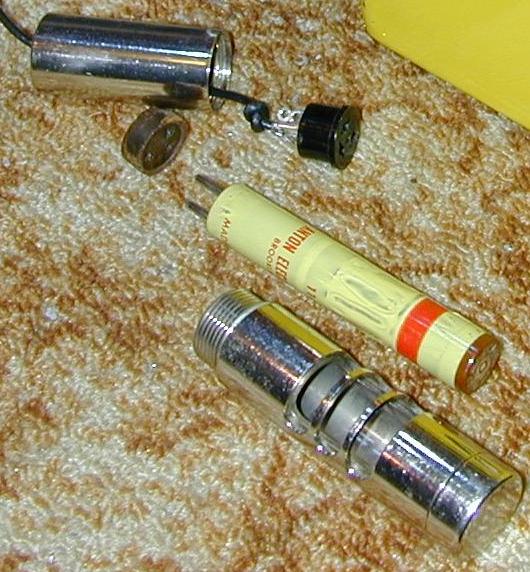
Disassembled Geiger Counter Probe Assembly
The probe from my CDV700 geiger counter had a worn out probe wire, moving it would cause false clicks from the counter, or no readings at all. The remedy was to rebuild the probe assembly. The rebuilding process follows:
Unscrew the top of the probe from the bottom by twising counter-clockwise until the two parts come apart. Don't be confused by the beta shield in the middle of the probe, it turns freely. The geiger tube should be connected to the bottom of the probe assembly at this point.
Gently rock and pull the 6993 geiger tube from its base until it comes out of the socket. This may take a while, be careful since the tube is fragile, it is also the most important component in the whole unit.
There is a brown rubber plug between the geiger tube and the 3-pin black amphenol socket. Push a small flat screwdriver around the edge of the rubber plug to loosen it from the sides of the probe, then use a needle nose pliers to gently pull the plug from inside of the probe.
The original wire is tied in a knot at the bottom of the probe and glued in with hard gray potting compound. Clip the wire off at the base of the probe.
The black 3-pin Amphenol tube socket is soldered to the glued-in wire. It can be removed by gently twisting to the left and right until the original wires break off. Do this by putting small needle nose pliers into 2 of the socket holes. Don't get too agressive, the socket is brittle and can easily break. The socket pins can also break. In the worst case scenario, if the socket breaks, it should be possible to solder the wires to the geiger tube pins, or to what's left of the socket pins. Be sure to observe which wire goes to which pin. If you lose track of which wire connects to which pin, some live experimentation can be used to figure out which connections make the counter work. Beware of the 900 Volts across the wires when the counter is on.
Once you have removed the socket, remove as much of the potting compound as is possible. I used a 1/8" drill on the back side of the probe to drill out the old wire, then took a 1/2" drill and drilled out the bulk of the potting compound from the inside. This should be done in a drill press, wrap the bottom of the probe in duct tape and hold the probe steady with pliers to avoid scratching the chrome plating. It is not necessary to drill all the way to the metal.
Choose a new piece of probe wire. It should fit through the hole at the bottom of the probe, and should be able to withstand operation at 900 volts. I used stranded 1/8" RG174 miniature RF coaxial cable for my probe. Common RG58 coax can also be used, the type with the stranded center conductor is recommended since its more flexible. The probe wire should be about 3 feet long. A useful modification to the counter is the addition of a BNC connector in place of the direct wire connection, RG174-compatible BNC connectors are available.
Feed the probe wire through the bottom of the probe hole. Strip off about 3/4" of the outer insulation. Unravel the coax shield wires, twist the shield together and tin with solder. Strip about 3/16" of inslation from the center conductor, twist and tin with solder. Tie the end of the coax wire into a small knot, tighten the knot by pulling on the wire with pliers. Only a small amount of wire should stick out of the top of the knot. Solder the center and shield wires to 2 of the 3 pins on the socket, use the same pins as the original wire. Make sure the socket fits into the bottom of the probe, adjust the knot if necessary.
Plug the geiger tube into the socket and test the counter to verify that it is wired correctly.
Mix up a small amount of quick-set epoxy glue. Coat the entire wire knot with a glob of the epoxy. Pull the socket and knot into the bottom of the probe, make sure the socket is seated at the lowest position. Try to avoid getting any epoxy on the sides of the probe during this operation. Twist the wire to spread the epoxy around the bottom of the probe. It may be necessary to apply a small amount of glue to the wire from the bottom of the probe to get a water-tight seal. Use a tissue to soak any excess epoxy off of the wire where it exits the probe. Place the probe in a vertical position and let the epoxy harden. You may want to place the rubber seal and geiger tube into the probe assembly and screw the top back on before the glue dries. Be careful not to get any glue on the geiger tube.
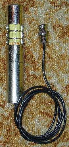
Completed Geiger Counter Probe Assembly
A BNC probe connector is a useful addition to the CDV700 geiger counter, it allows multiple probes to be used and allows the probe wire to be repaired without opening up the counter.
To add the BNC connector, open up the counter and remove the six screws that hold the two battery holders. Remove the two set screws from the range select switch. Gently rock the circuit board and pull the board away from its normal position. The phone and meter wires prevent the board from being removed completely.
Unsolder the probe wire from the circuit board and ground clip. Cut the probe wire where it goes through the case. Unscrew the aluminum pressure screw from around the probe wire. Loosen the washer that is under the pressure screw, and pull out the rubber water seal grommet that is around the wire.
Drill the old probe wire hole in the counter's top panel using a 3/8" drill, you may need a different sized drill for your particular BNC jack. A drill press and cutting oil is recommended.
Solder two 2" pieces of wire to the connections on the BNC jack. Put heat shrink tubing around the center conductor of the jack. It may be necessary to solder the ground wire directly to the jack's metal, file the flat guide edge of the jack's threaded side through to the brass metal, then solder the wire to the brass. Make sure the jack still fits through the drilled-out hole.
Make sure the jack and wires fit into the counter face. Clean any oil and dirt from the BNC jack and the mounting hole. Apply a thin coating of quick-set epoxy glue to the inside of the mounting hole and to the outside of the jack. Glue the BNC jack into the hole. Try to avoid getting glue on the jack wires. Align the jack in the hole and wait for the glue to harden.
Solder the jack wires to the ground tab (shield) and the high voltage PCB connection (center). Add a BNC connector to your geiger probe and verify normal operation.
If you have the appropriate metal tap, tapping threads into the counter is preferable over gluing a BNC jack to the counter. With a threaded jack, no ground wire is needed since the connector is grounded to the case via the threads. A reader send me these drill/tap sizes: drill the BNC hole with either an 11/16" or a 21/32" drill, then tap with a 3/8"x32tpi tap. Use Lock-Tite on the BNC connector threads to secure the connector.
Reassemble the battery holders, circuit board, and range switch knob.
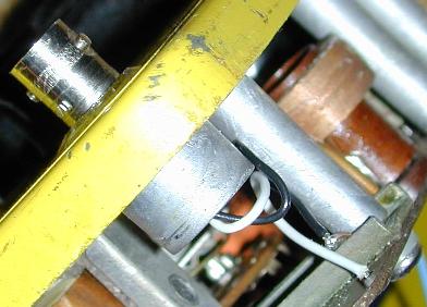
BNC probe connector added to a CDV700 Geiger counter
Back to FC's Geiger Counter Circuits page.