(C) 2015-2023, G. Forrest Cook, W0RIO (formerly WB0RIO)
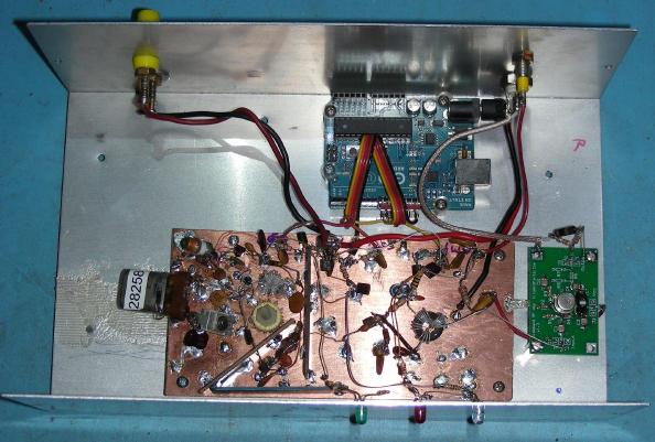
The beacon's 28Mhz exciter, RF amp and Arduino controller
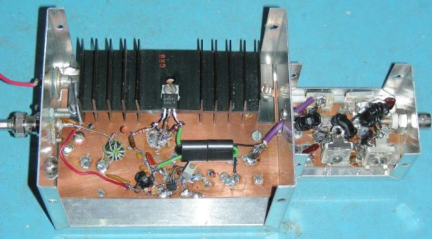
The beacon's 28Mhz 5W MOSFET RF power amp and low-pass filter
![]()
Schematic of the 28Mhz exciter, RF amp and keying stages
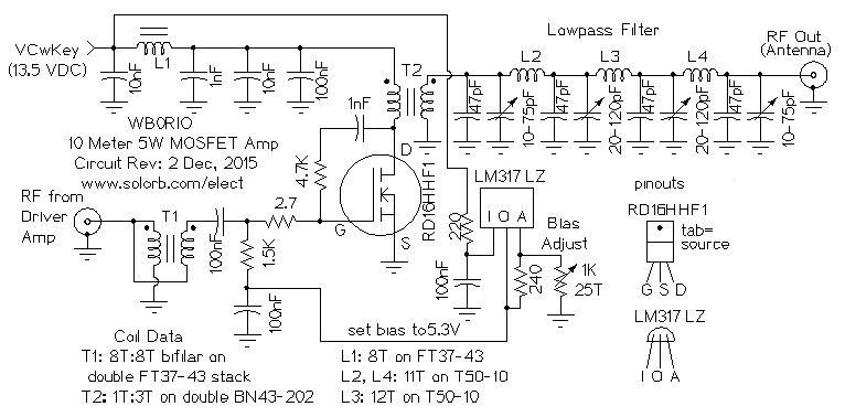
Schematic of the 5W 28Mhz RF amp and low-pass filter
This project involves the construction of a 5 Watt Morse code beacon transmitter that operates in the 28.200 to 28.300 section of the 10 Meter Amateur Radio band. Beacons continuously transmit a repeating message. Amateur radio operators listen for beacon signals in order to determine if long-distance propagation conditions are happening on the band.
The beacon controller uses an older Arduino Diecimila board with an Atmega 168p microprocessor for producing the three signals that control the transmitter. The project is also an experiment in using Frequency Shifting CW (FSCW), or two-tone Morse code. After the listener goes through a bit of a learning curve, FSCW can be decoded more easily than regular Morse code when low signal to noise conditions exist.
The beacon's 5W RF power amp is a separate module that can also be used as the output section for 12 meter (25Mhz) and 15 meter (21Mhz) low-power (QRP) transmitters.
The Arduino microprocessor is programmed with this simple Arduino beacon sketch. The sketch contains a generic test message. A custom message with your own call sign can be created with the cw2hex C language program which is available on my free software page. This utility was also used in my earlier EPROM-based beacon keyer project.
The three control signals from the Arduino include Osc. Enable (Digital 10), FSCW (Digital 9) and CW Keying (Digital 8). The beacon transmitter and the Arduino are both powered by a 12VDC (nominal) power source. At 13VDC, the idle current for the Arduino and transmitter is 45mA and the active current is 160mA.
A small solar power system could be used to provide the 12VDC used by this device. To further reduce the beacon's power consumption, it is possible to remove the Arduino Atmel processor chip from the Arduino board and run the chip with some minimal support circuitry. This LFO project shows an example of running the Arduino's processor chip without the Arduino board.
Three level-shifting circuits are used to convert the 0-5V control signals into 0-12V signals for operating the transmitter. The first two level shifters use a 2N2904 transistor to activate a 2N3906 transistor. The third level shifter replaces the 2N3906 with an IRF9540 P-channel MOSFET. The MOSFET has a lower voltage drop than the 2N3906 which maximizes the RF power output from the power amp. An IRFD9010 was originally used here, but the IRF9540 has a lower on-state resistance which helps to increase the power output from the RF amp.
The oscillator circut uses a 28 Mhz overtone crystal in a Pierce configuration. The basic circuit was found in the ARRL publication: W1FB's QRP Notebook. The oscillator features a VXO capacitor for adjusting the base frequency and an FSCW control input was added to allow for lowering the frequency during dashes. Note that there is a typo in the W1FB schematic, the impedance of L1 should be around 1.3K, not the 1.3 ohms shown. Testing at 28 Mhz showed that an L1 impedance of around 1K produced a more stable VXO range.
Several different oscillator circuits were tried before using the Pierce circuit. Its output level is lower, but it produces much less harmonic energy. Some oscillator configurations may cause the overtone crystal to oscillate at a different resonance frequency.
A 28.258 Mhz (nominal) overtone-type crystal was used in the oscillator, the actual VXO frequency range was 28.269 Mhz to 28.273 Mhz. eBay can sometimes be a good place to find 28 Mhz crystals.
The output of the VXO is sent to an MPF102 FET buffer circuit. The buffer has negative gain, but it greatly reduces the oscillator frequency shift between key-up and key-down conditions. Both the Oscillator and Buffer circuits are powered by a 78L08 voltage regulator which increases the oscillator's frequency stability.
The first RF Amp stage uses a 2N4401 transistor biased to run in class A. This stage boosts the 28 Mhz signal up enough to drive the power amp. The RF Amp's output is fed through a tuned RF transformer to reduce undesired harmonics. The collector circuit on the RF Amp includes a simple RC waveshaping network to eliminate keying clicks.
The RF Driver Amp uses the Kits and Parts.com Version 1.3 Wideband RF Amp kit. They also sell the toroid cores used in this project. The driver amp uses a 2N5109 transistor biased to run in class A. The amp's output is lowered to the level required by the RF power amp by using a 220 ohm resistor in series with the VCwKey supply. The 3dB pad on the output of the amplifier stabilizes the input of the power amp.
The RF Power Amp uses a Mitsubishi RD16HHF1 MOSFET transistor as the active device, it is available from RF Parts Company. The MOSFET is biased to run in class A when transmitting. The power to this stage is keyed so that it does not consume power when it is idle. Transformer T1 raises the impedance of the 50 ohm driver amp signal to better match the impedance of the MOSFET's gate. Transformer T2 raises the impedance of the MOSFET's drain circuit to match the input impedance of the low pass filter.
The 1nF capacitor and 4.7K resistor across the MOSFET gate and drain provide a small amount of negative feedback which lowers the amplifier's distortion. The LM317 LZ variable voltage regulator provides an adjustable bias voltage for the MOSFET transistor.
The output of the RF Power amp is fed through a 7 element low-pass filter to reduce the harmonic output level. When the low-pass filter is properly adjusted, the first harmonic is about 44dB below the carrier and the second harmonic is 60dB below. Common lowpass filter designs found on the net use fixed capacitors and inductors. Those circuits would work here, but having adjustable capacitors allows the amplifier to be tweaked for lower harmonics and higher power. Both type 10 and type 6 powdered iron cores were tried in this filter, similar results were found. If you use T50-6 cores, the turns counts should be 9-10-9 compared to the 11-12-11 for the T50-10 cores.
The level shifters, oscillator, buffer and RF Amp stages were built on a single piece of blank circuit board material using the ugly construction method. Many of the oscillator's components were physically stabilized by using 10M 1/2W resistors as standoffs, the oscillator coils were secured to the circuit board with hot-glue.
Small strips of blank circuit board material were soldered vertically to the main board to act as circuit isolation shields. Shields were placed between the oscillator and buffer and the buffer and the RF Amp.
The Power Amp was installed in a separate metal box. BNC connectors were used for the input and output terminals and the VCwKey signal was sent through a feed-through capacitor and ferrite bead mounted on the box. A separate ground connection is run between the power supply and the RF Amp box to provide good current flow and maximum power output. The MOSFET transistor is bolted to a fairly large aluminum heat sink, heat conducting grease should be used between the transistor and heat sink.
The low-pass filter was contructed in a small metal box that was mounted on the side of the power amp box. Several holes were drilled into the side of the low-pass box to allow the variable capacitors to be adjusted while the box is closed.
The RF Power Amp's bias adjustment should be set for 5.25V before doing any other testing on the beacon. Beware that adjusting the bias much higher than this will cause the RF output transistor to run hot or possibly burn up. If the heat sink becomes too hot to touch, reduce the bias voltage.
Connect the RF Out signal to a 50 ohm dummy load and place a high impedance oscilloscope probe across the load. An oscilloscope with a minimum of 100 Mhz of bandwidth should be used to monitor the output signal. Adjust the four variable low-pass filter capacitors for the highest amplitude and the most pure sine-wave output waveform. The capacitors are interactive and the adjustments should be made several times.
Most beacon messages start with a solid tone, followed by the station ID and grid-square location. During the tone part of the message, use a calibrated receiver to adjust the VXO control for the desired base frequency. Adjust the FSCW control while the Morse code message is being sent. The FSCW shift should typically be set somewhere between 25 Hz and 50 Hz. Tune the receiver so that it produces a fairly low tone, around 500 Hz. Adjust the FSCW control until the change in the tone of the dashes is noticeable.
The beacon transmitter should be connected to an antenna that is resonant at or near the beacon's transmit frequency. An antenna analyzer or SWR meter may be used to adjust the antenna resonance. Use the shortest feedline possible to reduce power losses. Most beacon transmitters use a vertical antenna for an omnidirectional radiation pattern. Once the transmitter is operational, it is a good idea to monitor the signal from a distance using a mobile receiver or ask a nearby ham friend to give you a signal report.
The FSCW beacon is intermittantly operated at 28.2715 Mhz, typically from dawn to dusk using either a 20 meter or 40 meter dipole antenna via an antenna tuner. The current message is roughly: *tone* DE W0RIO/B /FSCW DM79IX *pause* *tone* DE W0RIO/B W0RIO/B W0RIO/B DM79IX *pause*. The first part of the message uses the FSCW mode and the second part uses regular single-tone CW, the triple call sign helps automated beacon tracking stations on the Reverse Beacon Network decode and report the signal. Reception reports are always appreciated.
Bill Hays, Amateur radio station WJ50, is the former IARU Region 2 beacon coordinator. He has provided a web page with all kinds of 10 meter beacon information, including a list of active beacons. New beacons in the US should register their transmitter with the current coordinator Dennice Stice (WI5V).
I have been experimenting with using my DAS1 Dark Activated Switch kit to activate the beacon only during daylight hours. The DAS1 requires a simple modification to turn it into a Light Activated Switch.

FSCW and normal CW signal from the W3PIE KiwiSDR receiver in Jumonville, PA
Back to FC's Ham Radio Circuits page.