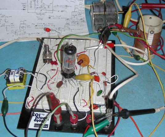
Prototype of the 6AR8 modulator circuit
(C) 2019, G. Forrest Cook W0RIO
Prototype of the 6AR8 modulator circuit
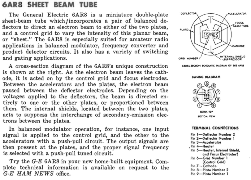
Description of the 6AR8 from GE Ham News
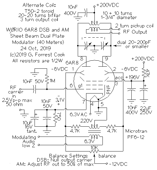
Schematic of the 6AR8 modulator circuit
The 6AR8 dual plate "sheet beam" tube was introduced in the mid 1950s and was intended for use as a synchronous detector in color TV chroma demodulator circuits. The tube is built with two deflection electrodes and two plates, which can be used to form a balanced mixer with differential inputs and outputs. Some circuits (not this one) use the cathode and control grid as an oscillator, the tube is roughly comparable to a modern NE602/SA602 IC.
This experiment involves using a 6AR8 as both a dual sideband (DSB) and amplitude modulation (AM) modulator at 7.2 Mhz, the 40 meters ham radio band. If the balance control is positioned to null the RF carrier signal on the output, DSB modulation can be produced. If the balance control is set to produce 50% of the maximum carrier signal on the output with no modulation, AM modulation can be produced.
The circuit could be used directly as a low-power DSB/AM transmitter, although it might be better to use it to drive a small linear amplifier output stage to achieve a bit more power. For more permanent construction, the circuit should be built into a shielded enclosure. A lowpass filter would also need to be installed between the output and the antenna to reduce harmonic emissions.
This project involves the use of potentially lethal high voltages including 120 VAC and 200 VDC. The project should only be taken on by someone who has experience working with high voltage circuitry. The power cord should always be removed and the power supply capacitors should be discharged when working on the circuit.
The 200VDC B+ supply, 6.3VAC filament supply and -12VDC bias supply are not shown, laboratory bench supplies were used. A Heathkit IP-17 regulated high voltage power supply was used for the 200VDC and 6.3VAC voltages and an adjustable DC supply was used for the -9V bias voltage. The Heathkit supply was powered through a 12VAC "buck" transformer to accomodate the modern higher line voltages (125VAC vs 115VAC) and keep the filament voltage output close to 6.3VAC. Note that pin 5 of the tube's filament circuit should be connected to ground, it is connected to some internal shielding elements.
The tube base diagram for the 6AR8 looks a lot like a pentode, but there is only one actual grid (G1), so the tube has more in common with cathode ray tubes and Magic Eye Tubes. The accelerator element should not be confused with a pentode's screen grid, it consumes little current and can be connected directly to the B+ supply.
In this circuit, the accelerator is biased with a 47K resistor to the B+ line and has a 10nF capacitor to ground to act as an RF bypasss. A significant amount of the modulation signal shows up on the accelerator pin, the 22uF capacitor levels that out. The accelerator element can be used to limit the maximum swing on the two plates by de-focusing the sheet beam. With 100V on the accelerator, fairly strong but rounded clipping was observed on the output waveform. This circuit runs the accelerator element very close to the B+ voltage for minimal clipping.
It should be noted that the 6AR8 is sensitive to magnetic fields and should be kept away from power transformers and anything magnetic. I did some tests with a fixed magnet and a tape head demagnetizer, it was possible to upset the tube's bias with the fixed magnet, the demagnetizer did not produce any significant change in the tube's balance after it was run near the tube.
The control grid (G1) is biased to ground through a 1M grid leak resistor and the RF carrier is sent to G1 through a 10nF DC bypass capacitor. A 2.5V p-p 50 ohm RF signal (12dBm) produced the highest RF output from the tube before compression and clipping took place.
The cathode circuit is fairly standard, the 750 ohm resistor raises the cathode up to 3.2V with a B+ of 200VDC and no RF input, this biases G1 near the center of the tube's linear region. The 10nF capacitor across the cathode resistor bypasses RF to ground and the optional 10uF tantalum capacitor bypasses audio frequencies to ground. Note that changing the voltage on the accelerator affects the cathode current and the resulting grid bias voltage.
The two deflection elements are driven in a differential mode by the primary side of a center-tapped split-bobbin 220V/6V filament transformer. The 4.7K resistors in series with the transformer combine with the transformer's winding resistance and the 10K potentiometer to form a resistive bridge circuit that can vary the DC bias between the two deflection elements. The -12VDC bias supply is applied to the center tap of the potentiometer. The typical deflection elements bias is around -6V, or -8V relative to the cathode, which is the range where the deflector is most responsive. Note that many 6AR8 designs bias the deflection elements at positive voltages and also apply a signal to only one of the two deflection elements.
Input to the deflector transformer comes from a low impedance audio source such as a low power audio amplifier which would be suitable for driving an 8 ohm speaker. In the test circuit, I used a low power tube amp driving an 8 ohm resistor in parallel with the 6V transformer winding. If the circuit is used as part of a transmitter, it would be a good idea to provide some audio filtering and compression to the signal to keep the bandwidth narrow and improve the "talk power". Typical ham radio transmit filters pass audio between 300Hz and 3.5Khz.
The output tank circuit is also wired in a differential configuration. The tank coil provides B+ to the plate through a center-tap that is bypassed to ground with a 10nF capacitor. A dual section variable capacitor is used to resonate the tank circuit at the desired output frequency, 7 Mhz in this case. The RF output from the mixer comes from a 2 turn link coil that is placed around the center of the tank coil.
Two NOS RCA 6AR8 tubes were tried in this circuit and both showed an imbalance toward the same plate. Both the deflector and plate leads were swapped, but the imbalance stayed on the same side of the tube, implying that it was a characteristic with the tubes, not the prototype circuit layout. I originally tried adding a 27pF silver mica capacitor across one section of the output circuit's variable capacitor to offset this balance but decided that a better solution was to increase the bias range on the deflection elements.
To calibrate the circuit for DSB usage, connect an oscilloscope to the pickup coil on the output tank coil to observe the output signal. Connect an RF source to the G1 circuit and set the level to around 12dBm. Disconnect any modulation signal from the input transformer. Adjust the balance control for the minimum carrier output level. Apply a modulation signal to the input transformer. Listen to the signal on a nearby SSB-capable ham radio receiver. Adjust the modulation signal below the point where distortion is heard. If you tune the receiver around, there should be no audible carrier. In the test setup shown, a small amount of residual carrier was caused by leakage from the RF input leads and lack of a shielded enclosure.
To set up the circuit for AM modulation, disconnect the modulation dignal and set the carrier balance control so that the output carrier is at around 50% of the level that it reaches at maximum imbalance. Connect the modulation source and listen to the signal on a short wave AM radio. Adjust the modulation signal below the point where distortion is heard. If you listen to the signal with an SSB receiver, you should be able to tune around and hear a definite carrier.
It would be easy to add a switching arrangement to select between two balance pots, this would allow the circuit to easily be changed from DSB mode to AM mode.
The circuit was built on a modern IC prototyping board. The tube sockets, transformer leads and various other components had 22 gauge solid wires attached to accomodate the holes in the proto board. Test leads with alligator clips and short wires were used for connecting the output tank circuit components.
A more permanent version of the circuit could be built, it would be a good idea to install everything in a shielded box. A tube shield should be used over the 6AR8 and the tank circuit should be inside of the shielded enclosure or in its own metal box.
The 6AR8 was mass-produced in the early 1960s and new old stock (NOS) tubes are readily available on eBay and from vacuum tube dealers. It has little value to tube hi-fi enthusiasts and can be purchased for low prices, $5 for a NOS tube is typical. The modulation transformer is a common split-bobbin type that can be found at several large electronic distributors. Tube sockets and high voltage capacitors can be purchased from various mail-order outlets.
There are a number of other sheet beam tubes that have similar characteristics to the 6AR8. The 6JH8 is apparently an improved version of the 6AR8, it has more gain and higher plate dissipation, it uses a positive deflection plate bias compared to the negative bias used in the 6AR8. The 6ME8 and 7360 tubes are also similar, they require higher deflection plate bias voltages. The 6ME8 also uses +350VDC on the accelerator with a b+ value of 250V.
Back to FC's Ham Radio Circuits page.