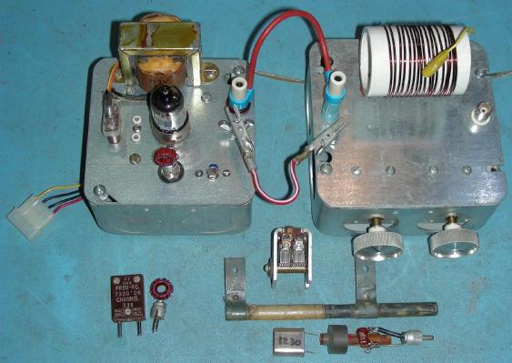
AM Chickadee transmitter top view with crystals and coils for several bands
(C) 2012-2020, G. Forrest Cook, W0RIO
AM Chickadee transmitter top view with crystals and coils for several bands
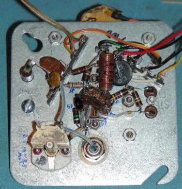
AM Chickadee transmitter wiring
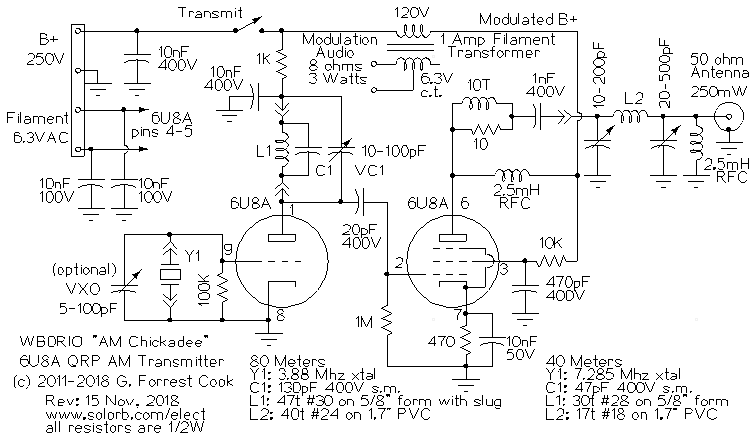
AM Chickadee schematic
The AM Chickadee is a one-tube Amplitude Modulation (AM) transmitter with an unmodulated output power of around 250 mW (1/4 W). This project is a descendant of the Little Chickadee QRP Morse code transmitter. The transmitter can be used for several purposes. First, it can be used to transmit a signals that can be picked up by a nearby short-wave or AM broadcast radio. The transmitter has been used for testing and listening to music on my collection of antique short-wave radios. Second, it can function as a low power (QRP) ham radio AM phone transmitter for use on the 80 or 40 meter ham bands.
If this circuit is used as a ham radio transmitter, the range will be very short due to the low power. The transmitter could be used for contacting other ham radio operators in the same neighborhood or a small town. For ham use, it would be a good idea to use an efficient tuned antenna such as a resonant dipole. A microphone preamp and push-to-talk switch would be required.
The AM Chickadee can be operated on frequencies outside of the ham bands by connecting the transmitter to a 50 ohm dummy load, a short piece of wire connected to the hot end of the the dummy load will provide a few tens of milliwatts of radiated power, which is plenty of signal for pickup on nearby radios. When transmitting music, it is important to pick a clear frequency, this will prevent other stations from interfering with your signal and will also ensure that you don't interfere with any other users of the frequency.
Older short wave radios cover one or more frequency ranges in the short wave bands. Bands covering 2-7 Mhz and 9 to 16 Mhz are common. It is best to stick to the lower end of the desired short wave band since older receivers tend to drift less at the lower frequencies. The 31 Meter short wave broadcast band from 9.4 to 9.9 Mhz is a good range of frequencies to aim for.
This transmitter may also be used to produce a signal in the AM broadcast band by making a few minor modifications to the circuit, details are below.
This project involves the use of potentially lethal high voltages including 120 VAC and 250 VDC. The project should only be taken on by someone who has experience working with high voltage circuitry. The power cord should always be removed and the power supply capacitors should be discharged when working on the transmitter.
A single 6U8A tube is used for the RF signal path, it contains a triode and a beam pentode in a 9 pin envelope. The triode section of the 6U8A is used as a tuned crystal oscillator stage. The triode's tuned plate circuit consists of L1, an inductor, C1, a fixed-value silver mica capacitor and VC1, an air-variable capacitor. Inductor L1 can be one of several types of coils, depending on the transmit frequency. L1 and the optional C1 have been installed outside of the main box on an insulated RCA jack, this allows different tuned circuits to be plugged in for operation on multiple frequencies. Keep in mind, L1 and C1 are electrially "hot" and should be covered.
A number of different junk-box crystals that oscillate on various frequencies have been used in the transmitter. These include 1.23 Mhz, 2.4 Mhz, 3.28 Mhz, 5.1 Mhz, 6.93 Mhz, 7.302 Mhz and 10.88 Mhz. Note that two crystal different crystal sockets (FT-243 and HC6/U) were wired in parallel, this allows multiple crystal types to be used in the transmitter. The 10.88 Mhz crystal was mounted on two pins from part of an old octal tube base, this allows a minature HC-49/U crystal to be plugged into the FT-243 socket.
The first version of this circuit used solenoid coils for L1 as noted in the schematic. Three additional versions of L1 were constructed using T50-2 toroid cores and #26 enameled copper wire. One coil has 17 turns of wire for 8-10Mhz, another has 34 turns for 5-8 Mhz and a third with 45 turns for 2-5 Mhz. The transmitter has also been used with a 1.23 Mhz crystal, which is in the middle of the AM broadcast band. For AM BC band operation, L1 can be a pi-wound AM broadcast band oscillator coil and C1 should be around 150 pF, depending on the coil and crystal used. See the photo above for an example of the AM band coils.
The output of the oscillator/amplifier triode is lightly coupled to the control grid of the 6U8A pentode through a 20 pF DC blocking capacitor. The pentode is wired as a class A RF amplifier, the DC bias current of the pentode is set by the 470 ohm cathode resistor. The output of the RF amp goes through a VHF parasitic snubber consisting of ten turns of wire around a 10 ohm resistor. Plate voltage is supplied to the pentode through a 2.5 mH RF choke coil, this isolates the RF from the power supply. Screen voltage is supplied by a 10K current-limiting resistor.
The output signal from the pentode stage is fed through a modular low-pass pi filter that matches the tube's high output impedance to the 50 ohm antenna impedance. See the Little Chickadee circuit for the filter details. The filter also greatly reduces the harmonic emissions from the transmitter. Note the 2.5 Mh "safety choke" on the output of the low-pass filter. It grounds out any high voltage DC components that may develop on the output circuit. The safety choke also keeps high DC voltages out of the input circuitry of a monitor oscilloscope.
A medium power audio signal comes from an external amplifier, it is used to drive one of the 3.15V windings on the modulation transformer, which is a re-purposed 6.3V 1A center-tapped filament transformer. The high-voltage line side of the transformer is inserted in series with the pentode's B+ line to produce the AM modulation.
An optional 22 ohm load resistor can be placed across the transformer's primary to produce a more resistive load for the audio amplifier, this may improve the audio fidelity, depending on the amp used. A converted Hammond AO-44 amp with a load resistor has worked well with the transmitter although it is a bit of overkill.
When using a tube modulation amplifier, the two transformers in series will have a low-pass effect and may introduce phase distortion into the audio signal. Despite this, a push-pull tube modulation amp driving the modulation transformer produces an acceptible AM signal. If you can find an appropriate one, some push-pull interstage transformers could be used between the tube audio stage and the transmitter's pentode plate circuit. That would require changing the typical speaker-side negative feedback circuitry used in many push-pull tube amp designs.
Solid-state amplifiers may also be used as a modulation amplifier, they have the advantage of only requiring a common filament transformer for modulating the RF amplifier. An LM383T IC amplifier running on 12VDC and wired in the Single Amplifier circuit from the LM383 datasheet has been used successfully. The audio amplifier section from an old mono car radio has also been used as a solid-state modulation amplifier.
The power supply for the transmitter is not shown, it should supply anywhere from 175 to 275 Volts DC at 30 mA and 6.3 Volts AC at 1 Amp. The higher B+ voltages will produce slightly more RF power. This power supply is normally used to power the transmitter. The supply is operated on the 320V setting and the transmitter loads the B+ voltage down to around 225V, producing 250 mW of carrier power and 1W of peak envelope power. Filament and B+ power is routed to the transmitter via a four wire PC disk drive power cable and a pair of 4 pin Molex connectors.
The transmitter was constructed on the cover plate of a standard 4"x4" electrical utility box, the plate had a knockout in the center that was perfect for mounting the nine pin tube socket. A few extra holes were drilled into the plate for the tube socket screws, the terminal strips, the output connector, the crystal socket(s), the oscillator tuning capacitor and the modulation transformer. A standard romex cable clamp can be used to secure the power and modulation wires to the box. Keep all wiring as short as possible to lessen the chance of creating spurious oscillations and other problems.
The modular antenna tuner / pi filter was built onto a 5"x5" electrical utility box cover plate and the assembly was mounted on top of a matching box. It is the same device that was used for the Little Chickadee transmitter and features pluggable 80 and 40 meter tank coils with additional coil taps. For operation on 10.88 Mhz, the 40 meter tank coil was tapped at 9 turns from the input side and the tap was shorted to the output side. The two variable capacitors are mounted inside of the filter box. The double-section variable capacitors in the pi filter were scrounged from old radios.
Two mini-switches were placed between the sections of each of the variable capacitors to give two capacitance ranges, only the smaller capacitor section is used when the switch is off. The switch on the plate side of the tank circuit should be left in the off position for frequencies above 5 Mhz. The output from the pi filter goes to a BNC jack that connects to an antenna or a dummy load such as a 50 ohm, 2 Watt carbon composition resistor.
When operating the transmitter on the AM broadcast band, the PI output filter is replaced with a ferrite loopstick antenna that is connected between the output side of the 1nF pentode plate capacitor and ground. The loopstick that was used consists of around 75 turns of wire on one end of a 3/8" x 5-1/4" ferrite rod. A 20-150 pF variable capacitor was placed in parallel with the loopstick coil. A common 365pF variable capacitor can also be used. The loopstick antenna should be sufficient for reaching nearby AM radios. If a greater coverage distance is desired, wrap a few turns of wire around the loopstick, ground one end of the this coil and connect the other end to a long wire antenna.
The triode circuit's tuning capacitor should be adjusted so that the circuit resonates at the crystal frequency. Initial resonance can be set by lightly coupling an oscilloscope probe to the oscillator plate circuit via a 5pF capacitor and tuning for the maximum signal. Final tuning should be performed by adjusting the triode circuit while adjusting the tank circuit's two capacitors. Note that the triode circuit won't oscillate unless its tuned circuit is set close to the crystal's resonant frequency or in some cases, the second harmonic of the crystal's frequency.
The second harmonic can be used for making another output frequency from a single crystal. The oscillator output power will be lower when tuned to a harmonic and the pentode amplifier's output will also be lower. If you are unsure about which frequency the transmitter is putting out, it can be verified by connecting a frequency counter across a 50 ohm dummy load on the output tank. An oscilloscope can also be used for checking the output frequency. A 1 Mhz signal will produce a 1 microsecond peak-to-peak waveform and a 10 Mhz signal will produce a 100 nanosecond p-p waveform.
Connect the transmitter to a sensitive SWR meter and connect the output of the SWR meter to an antenna or a dummy load. Most SWR meters will not be sensitive enough to measure the output of this transmitter, a ham radio QRP (low power) SWR meter should be used. A resonant dipole is a good choice for a short-wave antenna. Connect the power supply and modulation signals to the transmitter. Apply power and turn the transmit switch on. Adjust the pi filter for the best forward power on the SWR meter. The capacitor on the tube side of the pi filter should be adjusted for peak forward power and the capacitor on the antenna side should be adjusted to the point where forward power just starts to drop off. Checking the output signal waveform with an oscilloscope is recommended.
When operating this transmitter in the AM broadcast band, the output circuit should be changed from the circuit in the schematic to the loopstick circuit as explained above. Connect an oscilloscope to the secondary pickup coil on the loopstick and adjust the variable capacitor across the loopstick for the maximum waveform amplitude. if you don't have an oscilloscope, tune for the loudest signal on a nearby AM radio.
An easy way to set the level of the modulation amplifier is to monitor the signal on a good quality radio and adjust the level to a point below where distortion is heard. If you have an oscilloscope, attach it across a resistive dummy load that is connected to the antenna terminals and observe the waveform while modulating the transmitter. The waveform should be smooth and should never go to the zero carrier level, that indicates clipping of the signal.
An oscilloscope may also be used in X-Y mode to create a trapezoid pattern, which is a common way to monitor an AM transmitter. Connect the X axis to the modulation audio and the Y axis across the antenna terminals, adjust the X and Y gain for the largest display and adjust the modulation for the most triangular shape. The transmitter produced a very linear pattern when this test was done.
Most modern music sources produce a stereo signal. Two line-level audio signals can be mixed together to create a mono signal by feeding them both through low-value resistors into the modulation amp's input. I used two 2.2K resistors, but anything in the range of a few hundred ohms to about 10K should work. An optional but recommended audio compressor can be installed between the signal source and the modulation amplifier input. A compressor can help to prevent clipping and can also raise low-level passages in the audio. It is best to compress both channels with a stereo compressor, then mix the two compressed signals before feeding the modulation amp.
If you notice a lot of hum on the received signal, the transmitter's output may be getting coupled to an AC power line. The best way to avoid this problem is to locate the transmitter's output tank coil and antenna away from nearby house wiring and power cords. Receiver antennas should also be kept away from AC power wiring. With the transmiter turned off, the receiver hum can sometimes be minimized by rotating the receiver or moving external receiving antennas.
A well-stocked junk box is the first place to start, your author scrounged most of the parts for this project from discarded electronics. Tubes, sockets and power transformers can be found at Antique Electronic Supply or on eBay. Other parts can be purchased from Mouser, Newark, Jameco or Digi-Key. Any well-stocked hardware store will carry the electrical boxes and plumbing parts that are used in this project.
A ham radio license is required to transmit a voice signal in the ham radio bands. If you are broadcasting a low-power music signal, it is advisable to use frequencies that are not in use by anyone, and are outside of the ham bands, since you may cause interference to others.
If you want to operate the transmitter in the short-wave broadcast bands, a number of common crystal frequencies are available. Here are some readily available crystal frequencies: 5.9904 and 6.0 Mhz crystals are in the 49 Meter band, 7.3728 Mhz crystals are in the 39 Meter band, 9.8304 Mhz crystals are in the 31 Meter band and 11.981 and 12.0 Mhz crystals are in the 25 Meter band. These crystals are commonly available from mail-order suppliers such as Mouser, Digi-Key and Newark. Another good source for crystals is eBay.
If you intend to use the transmitter for a number of bands, capacitor C1 can have several values that are switched across variable capacitor VC1 to give a wider range or resonant frequencies. A miniature SPDT center-off miniature toggle switch and 91pF and 180pF silver mica capacitors can be added across VC1 to give three capacitance ranges, 10-100pF, 101-190pF and 190-290pF (plus stray capacitance).
If several different versions of the L1 plug-in toroid coils are made, the oscillator can be resonated across a range of around 2 Mhz to 20 Mhz. Several versions of plug-in Tank coil L2 can be built, and adjustable taps on L2 can be selected with a short clip-lead that connects to the output side of the coil.
It is possible to substitute several other types of tube in place of the 6U8A. 6GH8 and 6EA8 tubes have the same pinout as the 6U8A and both should work in this circuit with no modifications. Higher power triode-pentode tubes such as the 6AW8A and 6BM8 could also be used in this circuit with the appropriate pinout changes, lower value cathode bias resistors could be used on the pentode circuit of these tubes for higher power. One could also use separate tubes in a similar circuit to produce higher power levels. A 6C4 oscillator tube driving a 6V6 or a 6BQ5/EL84 should be able to produce several Watts of output power.
Back to FC's Ham Radio Circuits page.