(C) 2015, G. Forrest Cook, W0RIO (formerly WB0RIO)
|
|
|
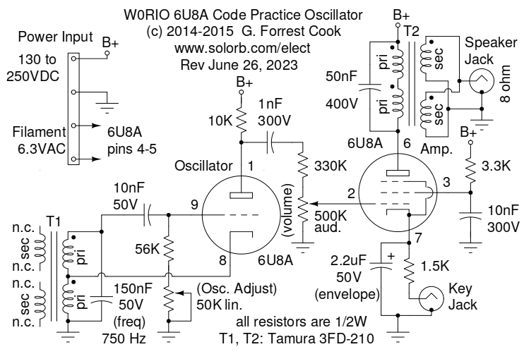
Schematic of the W0RIO 6U8A Code Practice Oscillator
This circuit uses a 6U8A triode/pentode tube as the heart of a code practice oscillator (CPO). It is simple enough to be built by a beginner and would be a good introductory project for those who want to experiment with vacuum tubes.
The circuit produces a hi-fi sinusoidal output with a wave-shaped envelope for minimal key clicks. These features reduce operator fatigue and make the CPO easy to listen to for extended periods. For contrast, see my solid-state Smooth Tone Clickless CW Sidetone Generator project.
The circuit is designed to work as a stand-alone unit. The design is modular and it would be fairly easy to adapt it to most tube transmitters as a sidetone oscillator.
This simple Power Supply for Vacuum Tube Experiments can provide power for the code practice oscillator. The power supply can be set to either the 130V or 320V settings, these load down to 130 or 255VDC when the CPO is keyed. The output volume will be higher with the higher voltage setting.
This project involves the use of potentially lethal high voltages including 120 VAC and 320 VDC. The project should only be taken on by someone who has experience working with high voltage circuitry. The power supply should always be disconnected and the power supply capacitors should be discharged when working on the code practice oscillator. The circuit's chassis should always be connected to the AC power ground when operating.
The triode section of the 6U8A is wired as an audio frequency Hartley oscillator. The oscillator's resonant components include the primary windings of a split-bobbin power transformer and a 150nF capacitor. The 150nF capacitor sets the frequency to around 750 Hz, which is a good tone for code practice. Other capacitor values can be used for different frequencies. The 150nF capacitor was constructed by wiring a 100nF capacitor in parallel with a 50nF capacitor. The Osc. Adjust trimmer potentiometer is used to set the DC bias on the oscillator, it should be set to the point with the maximum amplitude and minimum distortion.
I originally experimented with using the 6U8A triode in a phase-shift oscillator arrangement, that would have eliminated the need for an oscillator coil. I found that the 6U8A triode did not have enough gain to make that type of oscillator, a higher gain tube such as a 6AU6 pentode would work. Fortunately, the hartley oscillator can produce a cleaner sine wave than a phase shift oscillator.
The output of the oscillator stage is lightly coupled to the 500K volume control through a 1nF blocking capacitor and a 330K resistor. The volume control feeds the control grid of the 6U8A pentode section which is wired as a class A audio amplifier. The screen grid is pulled high by a 3.3K resistor and is bypassed to ground with a 10nF capacitor.
The amplifier is cathode keyed, the 2.2uF cathode bypass capacitor provides envelope waveshaping to reduce key clicks. Transformer T2 transforms the high impedance plate circuit down to low impedance for driving the speaker. The cathode keying circuit has about 15V on it, which will not present any shock hazard on exposed Morse code key contacts. It is possible to key this circuit with an open-collector NPN transistor, this can be done if you want to drive the oscillator from an automatic keyer.
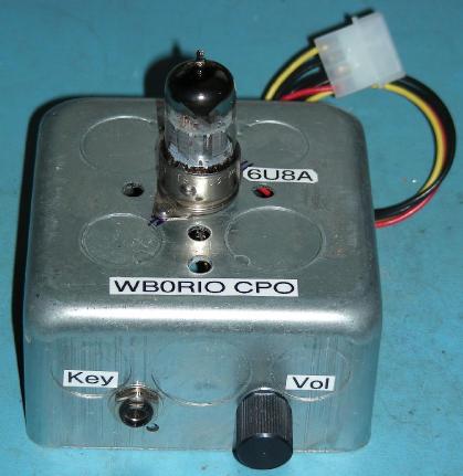
The code practice oscillator was built into a 4"x4"x2" electrical utility box. This type of box is normally used to mount two light switches. A solid box cover plate was used for the bottom of the box, rubber feet should be stuck to the plate to prevent scratching. If you can't find a box cover with the holes in the right place, it is easy to drill a few new holes in a standard 4"x4" cover plate.
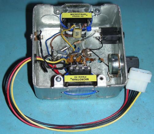
The 9 pin 6U8A tube socket was installed into a knockout hole on the top of the box, two holes were drilled for the socket mounts. Appropriate holes were drilled for the speaker and key jacks and the volume control. One multi-point terminal strip was installed inside the box and components were connected using the point-to-point wiring method.
The two transformers are held against the sides of the box using Panduit ties that loop through holes in the box. The power input wiring harness uses a standard 4 pin male PC power supply connector, these can often be found inside of junk computers. The associated power supply has an equivalent female connector.
A well-stocked junk box is the first place to start, your author scrounged most of the parts for this project from discarded electronics. Home Depot, or any well-stocked hardware store will carry the electrical boxes and cover plates.
The split-bobbin transformers are Microtran PSD2-10 or Tamura 3FD-210 types, they have dual 120V primaries and dual 10V secondaries. The transformers are available from Mouser, Newark, Jameco or Digi-Key. The Digi-Key part number is MT2096-ND. Note that a slightly different transformer (Microtran PSS2-10) is used for T1 in the above photo. The secondary of the PSS2-10 differs frorm the PSD2-10, but only the primary is used, so either part can be used.
Although it is no longer being manufactured, the 6U8A tube is still very common since so many were produced. The 6U8A tube and tube socket can be found at Antique Electronic Supply or on eBay. Pin-compatible substitute tubes include the 6GH8A and 6EA8.
Connect the power supply, Morse code key and a speaker to the code practice oscillator. Apply power to the circuit and let it warm up for a minute.
Adjust the volume control to the center of its range and press the key. Adjust the Osc. Adjust trimmer for the best tone, this is typically the point where the volume rises then levels off.
If the oscillator does not produce a tone, check your wiring and be sure that the transformer windings are connected with the correct phasing.
Different speakers can produce very different volume levels, it is a good idea to try a variety of speakers until you find one that sounds good to your ears. A 4 ohm speaker will be somewhat quiet due to an impedance mismatch, 8 or 16 ohm speakers are recommended. A standard un-amplified computer speaker will work well with this oscillator.
Once you have a working Morse code oscillator, start sending Morse code and work on improving your "fist".
Back to FC's Ham Radio Circuits page.