(C) 2017, G. Forrest Cook W0RIO (formerly WB0RIO)
This project involves building an isolated audio/PTT interface between a Ten-Tec Argo 555 SSB ham radio transceiver and a laptop computer. It allows the Argo to be used for transmitting and receiving PSK-31, RTTY, Olivia, Contestia, JT65 and other digital modes. The open-source program Fldigi is used for encoding and decoding the various modes. This interface is an expansion of the example circuits shown in the Fldigi documentation and has been derived from my earlier Kenwood TS-430s interface.
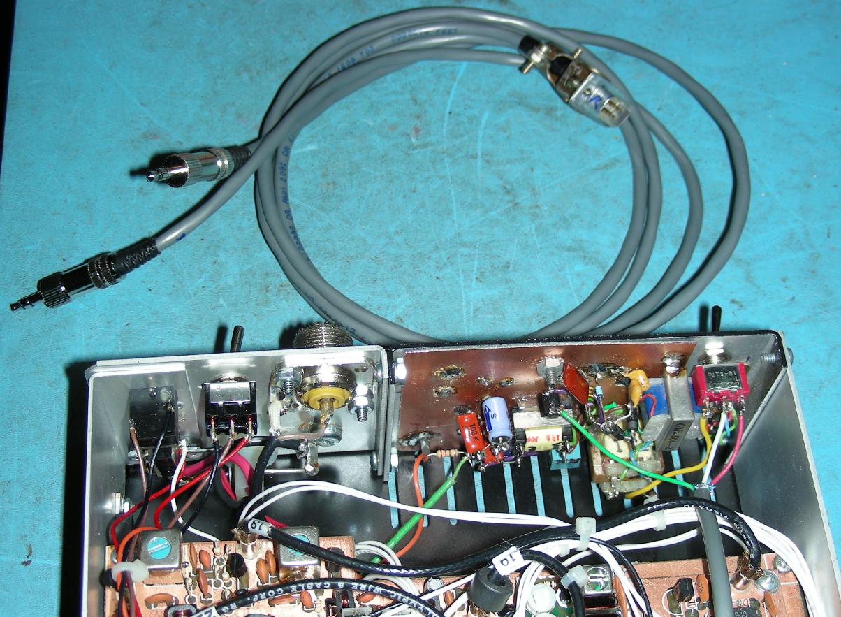
The Ten-Tec Argo 555 requires some simple modifications involving connections to the Mic input, the PTT line, the Audio Gain control and the switched 13.5VDC power circuit. The circuitry was built into the back of the Argo box as shown in the photo above. The audio interface cables connect to the Argo via a DE9 connector. The circuit should also work with the higher-power version of this transceiver, the Scout 556, it would need to be constructed in an external box. This interface could be adapted to work other SSB ham radio transceivers without many modifications.
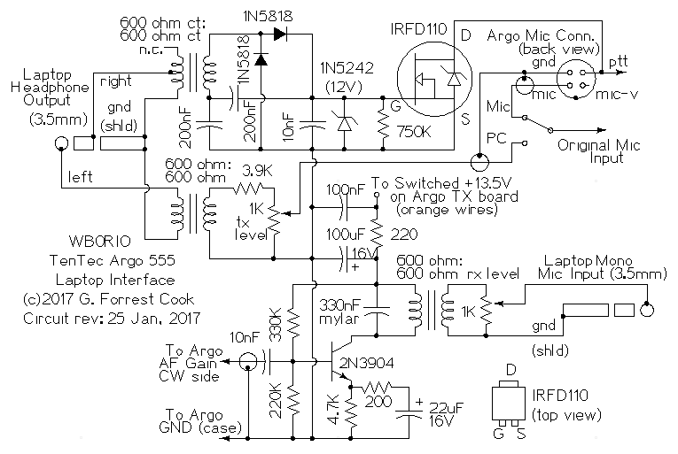
The transmit signal comes from the left channel of the laptop's headphone jack (tip to sleeve) and is fed to a 600:600 ohm isolation transformer. The level is reduced via a 3.9K resistor and adjusted by the 1K tx level trimmer potentiometer. The signal is then fed to the Argo microphone input via the Mic/PC Selector switch.
The push-to-talk signal comes from the laptop headphone right channel (ring to sleeve). When configured to do so, Fldigi sends a sine wave to this channel when it wants to transmit. The signal is fed to a 600ct:600ct ohm isolation transformer that is wired as a step-up device. The output of the transformer drives a voltage doubler/rectifier circuit that produces a gate drive signal for the IRFD110 MOSFET transistor. The IRFD110 drain grounds the Argo PTT line when the gate drive signal is active. The gate drive signal is limited to 12V by the 1N5242 diode and the 750K resistor drains the 10nF gate delay capacitor when the push-to-talk wave shuts off. Almost any N-channel MOSFET transistor will work in this circuit.
The receive signal comes from the high side of the Argo volume control. This allows the speaker audio to be turned up and down without affecting the laptop signal level. The receive signal is amplified by the 2N3904 transistor, which is configured as a class A amplifier. This stage also acts as a buffer so that the Argo audio line is not loaded down by the interface.
The output of the receive signal amp drives a 600:600 ohm isolation transformer which has a 330nF capacitor across the primary. The transformer/capacitor acts like a low-Q bandpass filter with a peak response at 500 Hz. This filtering action combines with the Argo's IF filter to pass a reasonably narrow band of audio signals to the laptop. The capacitor value may need adjusting, depending on the transformer used. The output of the receive signal transformer is attenuated by the rx level control before it is sent to the laptop's Mic input (tip-sleeve).
To adjust the resonance of the receive transformer circuit, disconnect the 10nF capacitor from the Argo AF Gain control and connect an audio sine wave signal generator to the line. Connect an oscilloscope across the RX level control. Adjust the signal generator's output level so that the oscilloscope signal does not show any clipping. As you change the signal generator's frequency, there should be a point where the sine wave amplitude peaks on the oscilloscope. If the peak is below 500 Hz, reduce the value of the 330nF capacitor, if the peak is above 500 Hz, increase the value of the capacitor.
The circuit was built onto a piece of scrap copper-plated printed circuit board material that was cut to fit on the Argo's empty back panel. The PC board was attached to the panel with two 4-40 machine screws. Holes for the PC board, the Input Select switch and the DE-9S Audio Line connector were drilled into the Argo back panel. A shielded multi-pin wire was used for connecting to the Argo microphone connector. Two stereo shelded wires connect to the DE-9P Audio Line connector on the Argo side and to 2.5MM stereo plugs on the laptop side. The DE-9 connectors are optional, the audio lines could also be routed into the back of the Argo and soldered directly to the PC board components.
All of the interface circuitry was soldered onto the PC board material using the "dead bug" style. Note that the PC board's copper is grounded to the Argo's case by the mounting screws. Some of the parts were adhered to the PC board using a hot glue gun, others were soldered directly to the board. Hot glue is not recommended if the rig is to be operated in a high-vibration environment such as a car. All of the parts used in this project were scrounged from the author's junk box.
All of the external wiring and the internal audio wiring was done with foil-shielded wire. The shield connections should be done carefully to avoid pickup of stray RF energy from the transmitter. Shields should generally only be grounded on one end and left floating on the other end to avoid ground loops. The cable from an old PC mouse can be a good source of multi-conductor shielded wire.
The connection to the Argo AF gain control was soldered directly to the back of the gain pot. Accessing this connection point required cutting a small notch in the side of the plastic front panel material. The notch is completely covered by the Argo's metal case, so it is not visible when the rig is re-assembled.
The Mic and PTT connections were soldered directly to the back of the Argo's Mic connector via a 3 wire shielded cable. The Mic line was un-soldered from the Mic connector and routed to the Input Select switch via the shielded cable. The other two shielded wires connect to the connector's Mic pin and the connector's PTT pin. The cable shield connects to the connector's GND pin.
DC power for the 2N3904 amplifier comes from the bottom of the Argo's TX amplifier board. In my Argo, the switched 13.5VDC power is routed with orange wire. The interface's power line was added to the bottom of the board where several other orange wires connect. If you are unsure about this connection, carefully probe for this voltage with the Argo power turned on.
Fldigi, or whatever software you use on the computer should be configured to output a push-to-talk sine wave on the sound card's right audio channel during transmit.
The PC's sound card mixer adjustments need to be set up. Connect the transmitter's RF output to a dummy load during this process. The sound card output level (the headphone and PCM level controls on my laptop) should be set and the levels should be noted. An oscilloscope should be connected to the laptop's audio output connections and a PSK-31 waveform should be transmitted. The sound card levels should be set so that the signal on the oscilloscope is about 10% below the point of clipping (flat-topping). Set the Argo's mic input level to 50% and adjust the tx level trimmer so to the point just below where the ALC LED starts to blink.
Note that the sound card's output level also controls the amount of gate drive on the PTT circuit. If you send too low of a level out, the IRFD110 gate drive voltage may drop below the activation level and the transmitter will shut off. A logic-level gate MOSFET such as an IRLZ44N can be substituted for the IRFD110 if a wider range of signal levels is desired.
The rx level trimmer should be set while monitoring live signals off of the air. A good place to find such signals is on the 20 meter Ham band from 14.070 to 14.073 Mhz. Run FlDigi or whatever modem software you have so that there is a waterfall display to observe. Turn the Argo's IF Bandwidth control all the way counter-clockwise. Turn the rx level trimmer to 50% and adjust the laptop's input mixer level until you see signals on the waterfall. Tune around until you receive a strong PSK-31 signal. Adjust the rx level trimmer and input mixer levels so that the background is blue and the active signals are red. It is better to turn the rx level down and the laptop mixer up to minimize the chance of input overloading. It is a good idea to write down the mixer settings for future usage. I have written a small Python program that sets all of the mixer parameters to a known state, this is specific to the sound chip in my laptop.
Keep in mind that the signal and noise levels can vary widely depending on which band you are using, the band conditions and the transceiver filter settings. Beware that some soundcard mixers may route the receive signal back to the output lines, activating the transmitter when strong signals are received. Careful adjustment of all of the mixer controls will prevent this issue. See the Fldigi documentation for more details on setting the levels correctly.
Connect the two audio lines between the Argo and the laptop's audio connections. Run FlDigi or your favorite digital-mode software. Tune into some signals and do some test monitoring to verify that the signals are being decoded correctly.
The Argo 555 is a minimalist SSB transceiver with just the most basic features, especially in the area of receive filtering. Digital modes require narrow receive bandwidth filters for the best results. The best way to get the most filtering with the Argo is to crank the IF Bandwidth control all the way to the left and adjust the PTO (VFO) control so that received signals fall in the 300-600 Hz part of the waterfall. You can widen the bandwidth control when hunting for new stations, move the VFO control so that the station is at 500 Hz before narrowing the bandwidth back down.
The stability of the Argo's analog PTO was a point of concern. So far, this has not been an issue with making contacts. When changing frequencies, it is a good idea to tap the PTO knob so that it "sets in" to a stable mechanical place. The longer-term drift of the PTO may be an issue with slow modes such as JT-65.
Before making contacts, the sound card's output level should be set to the sweet spot explained above, then left alone. The Argo's mic input control can be used to fine-tune the transmit level. The mic input level should always be set so that the modulation level is below the point where the transmitter's ALC LED blinks. Over-driving the transmitter causes wide-band splatter, which may interfere with other Hams. It also spreads the power away from your desired frequency, which reduces your effective transmit signal level.
Your author has made numerous successful PSK-31, PSK-63 and Olivia contacts with this interface. Running at only 5W can be difficult at times, especially when the band conditions are noisy. PSK-31 and especially modes like Olivia with forward error correction (FEC) can work surprisingly well at the 5W level. It is a good idea to pay attention to the SNR ratio and modulation info that remote stations send back to you.
Back to FC's Ham Radio Circuits page.