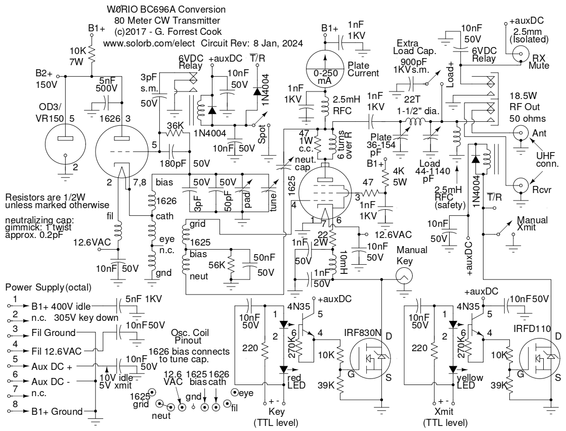
(C) 2017, G. Forrest Cook, W0RIO (formerly WB0RIO)
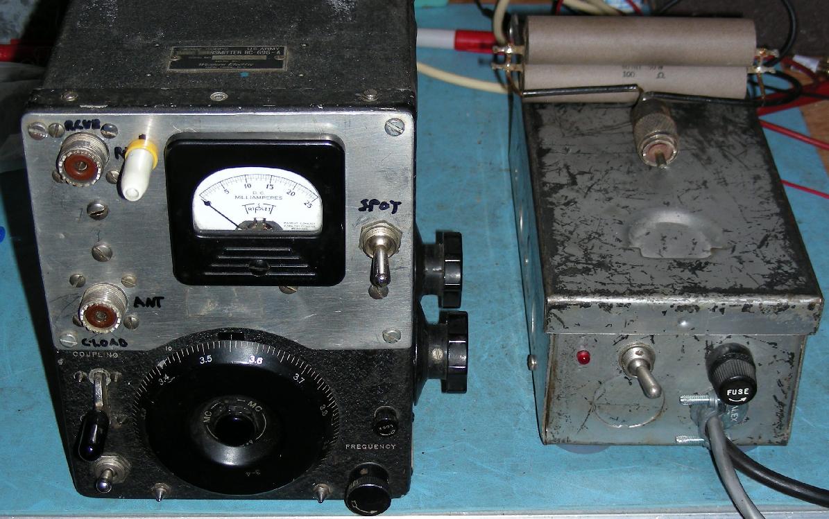
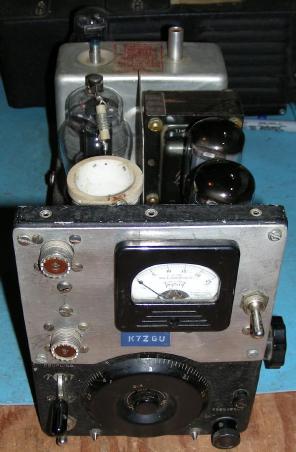
BC696A Front View, click for a larger image
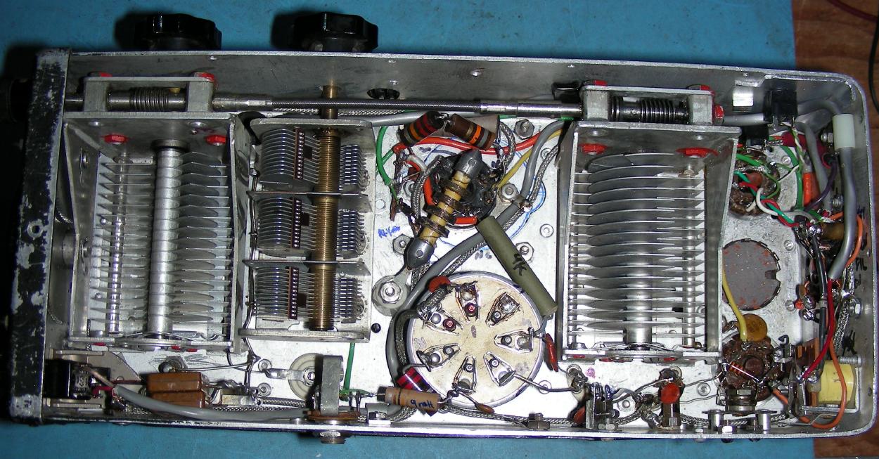
BC696A bottom View, click for a larger image
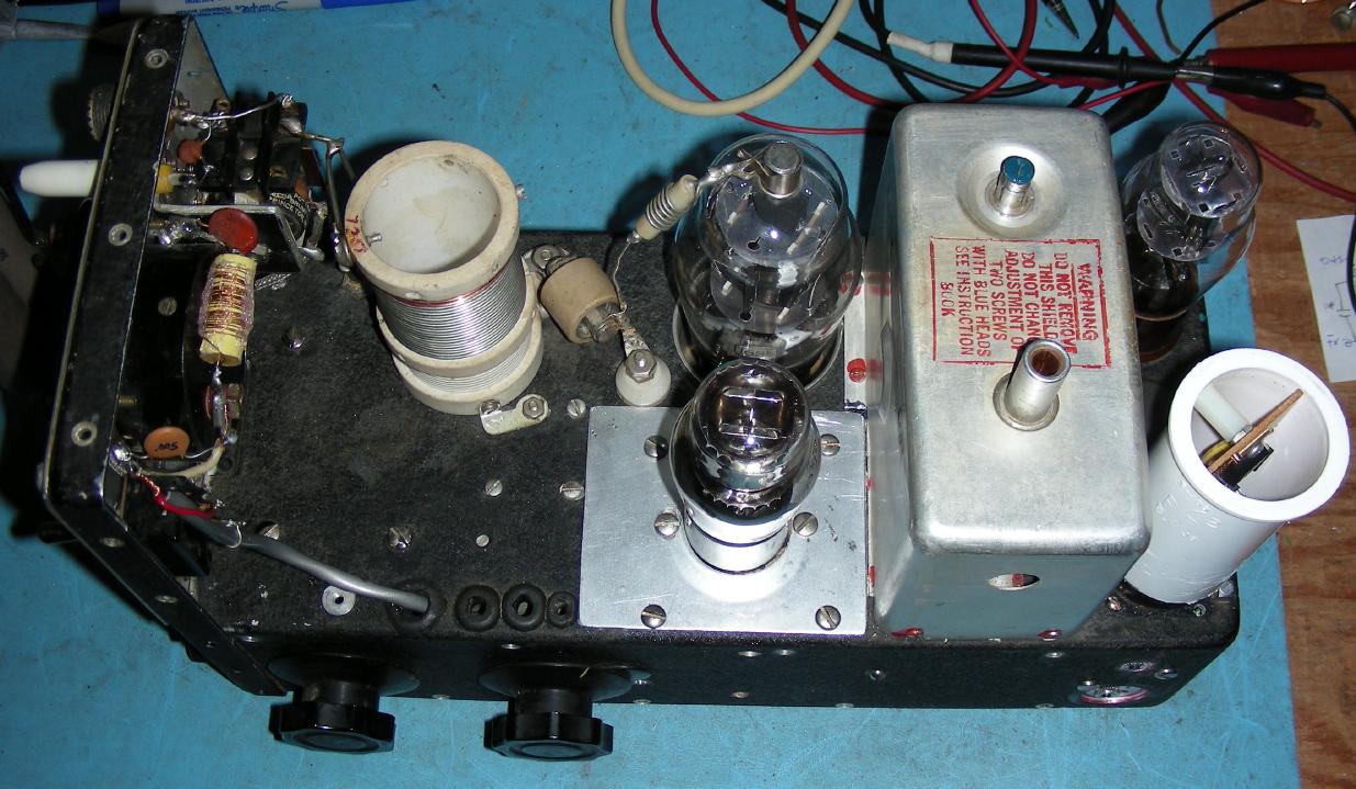
BC696A Top View, click for a larger image
This project involved the conversion of a modified BC-696A command set from an 80 meter AM phone transmitter into an 80 meter CW transmitter. The set had a sticker on the front panel for K7ZGU, a silent key ham operator who probably did the original modifications. Here are photos of the front and side of the transmitter as it was purchased.
My original intent was to reverse engineer the set and make it function again. I had no documentation or details on the power supply requirements. The set was built into the small chassis using many parts, including six tubes, four transformers and numerous passive components. It did not take long for me to realize that I had to remove many of the parts in order to figure out how the transmitter was wired. That eventually led to my decision to part-out the set and turn it into something new.
After removing many of the components, I briefly toyed with the idea of turning the set into a 40 meter CW transmitter. I powered up the still-intact oscillator section by itself and decided that the oscillator was not that stable at 3.5 Mhz and would be even more unstable if the frequency were doubled. The space to build a doubler or hetrodyne mixer was also too tight for my taste, so I decided to leave the rig on 80 meters and work on improving the stability of the oscillator.
As can be seen in the photo of the bottom of the set, the front variable capacitor had been disconnected from the mechanical tuning linkage and the middle variable capacitor had been replaced with a higher capacitance unit. The two variable capacitors and the modified inductor on the top of the chassis formed a standard PI output section. Four more turns were added to that inductor make the PI circuit tune better on the low end of the 80 meter band where it will be operated.
Here is a list of the features and capabilities on my version of this rig:
This project involves the use of potentially lethal high voltages including 120 VAC and 400 VDC. The project should only be taken on by someone who has experience working with high voltage circuitry. The power cord should always be removed and the power supply capacitors should be discharged before working on the transmitter.
As explained above, many of the original components were removed from the set and placed aside for future use. A lot of the interior wiring had been routed with un-insulated shielded wire. That wiring was left in place or pushed aside for later re-use. The radio had bypass capacitors installed in many locations, these were left in place wherever possible. The use of many bypass capacitors became one of the "themes" of this project, they are used on both ends of many control/filament lines and on most of the connectors to the external wiring.
Several aluminum plates and un-needed connectors and controls were removed. Most of the wiring was removed from the tube sockets with the exception of some of the oscillator wiring. All of the wiring was removed from the octal power-input plug. The output tank coil and associated variable capacitors, and the T/R relay were left in place.
The interior of the now-bare chassis was cleaned with an old toothbrush and dusted with an air gun. All of the high voltage components on the output circuit were cleaned using a toothbrush soaked with rubbing alcohol. All of the controls were lubricated and the variable capacitor, switch and relay contracts were cleaned with CAIG de-oxit spray.
At this point the rig was nearly bare, and the chassis looked like swiss cheese due to the many holes. The holes were filled with metal hole plugs, screws and nuts, and a few aluminum plates. The plate that covered the hole over the second 1625 tube socket from the stock BC696A was punched and an octal tube socket was installed for the gas regulator tube. A replacement octal tube socket was added back to the set where the original 1629 eye tube had been located.
A plate was cut out to cover the original microphone jack and that was drilled out to hold the two 3.5mm T/R and Keying connectors. A hole on the side of the rig was enlarged in order to hold the new 1/4" key jack.
The filament wiring was now added back to the set and connected to the octal power input plug using some of the existing coax wire. The filaments were wired in parallel so that they would run on 12.6VAC. The tubes were plugged in and filament power was applied to verify that the filament wiring was correct. Note that the 1626 filament wiring runs through the oscillator coils and the filament power is wired to the semi-circular coil connector. This unusual filament circuit was probably designed so that the 1626 cathode and filament were both operated at the same RF potential.
The remaining oscillator tube wiring was compared to the stock BC696A schematic, it was still in the original configuration. B+ voltage was applied to the plate of the oscillator tube, and a signal was observed on the output of the oscillator coil using an oscilloscope. I decided to run the oscillator on +150V, since that is a standard regulator tube voltage. The 1626 grid bias resistor was set to 36K, this is the point where the oscillator produced the maximum output with the B+ set to 150V. The 10K plate resistor on the 1626 triode was made with a series/parallel combination of resistors, it can be seen in the top-center of the underside photo as a 22K 2W and 18K 2W resistor in series across a 14K resistor. The plate side of this array connects to the unused pin 2 on the 1625 socket. The plate resistor is located away from the oscillator to reduce heating and VFO drift.
A 47 ohm grid stopper resistor with short leads was added between the 1625 screen grid and its bias supply. This prevents the 1625 screen grid from entering a negative resistance zone during keying and reduces key clicks and splatter on the transmitted signal.
The 25mA plate current meter had a home-made shunt resistor across its terminals. The meter was tested and found to read full scale (25) with about 150mA across it. A new shunt was constructed by wrapping numerous turns of #28 magnet wire over a capacitor. The new shunt was gradually un-wound until the full scale reading on the meter corresponded to 250mA. The meter was wired back into the plate circuit between the power input jack and the 2.5mH plate choke coil.
The VR150 regulator tube circuit and the 1625 screen grid circuit were added. The 150 volt line from the regulator tube was connected to the oscillator tube. Both of the dropping resistors were set to values that produced the desired operating currents. The 1625 grid bias circuit was rebuilt and a 56K bias resistor was found to produce the maximum signal and minimum chirp.
The output of the tank circuit was connected to a 50 ohm dummy load. The 1625 cathode circuit was experimented with while it was constructed. The 22 ohm series resistor gives a small amount of negative feedback without reducing the output power significantly, this keeps the amplifier distortion low. The 10mH cathode choke was found to greatly reduce the amount of chirp produced when the amplifier stage was keyed.
All of the filament and control line wiring was secured to the chassis in many places using cable clamps. The oscillator frequency was monitored on a receiver and the wiring was pushed and prodded using a plastic screwdriver. Any wires that caused the frequency to move were secured to the chassis with more clamps or tied to nearby wiring with panduit ties.
The manual key line was connected to the key jack and the T/R switch was connected to the Aux DC line on the power input connector. At this point, the set was operational in a manual mode.
|
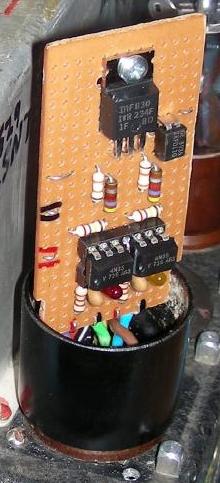
The solid-state keying module is an optional accessory, it allows the transmitter to be connected to an automatic keying and T/R sequencer. The keying module was assembled on a piece of perforated circuit board and connected to the pins of an old octal tube socket. A piece of 1-1/4" PVC sink drain pipe was press-fitted over the octal socket and a nylon spacer was used to secure the top of the keying module to the side of the pipe. The keying module was plugged into the unused 1629 socket and that was wired to the keying input jacks and other circuitry. |
The T/R frequency offset circuit was assembled on the bottom of the chassis close to the oscillator circuit. Short and rigid wiring was used to connect the offset capacitor between the relay and the oscillator circuit. The offset relay control line was routed to the front panel switch and to the power input connector.
|
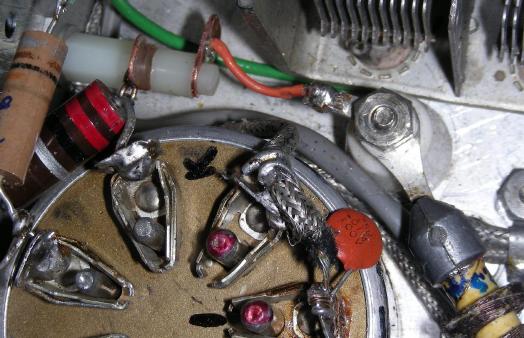
A neutralizing capacitor was added to the 1625 plate circuit. The capacitor should have a value of around 0.2pF. The first attempt involved making a "gimmick" capacitor that consisted of one twist of insulated solid wire connected between the plate circuit and the oscillator coil tap. This was replaced with a more easily adjustable home-made variable capacitor. The capacitor was built using two small oval-shaped copper pieces, two nylon spacers and a nylon screw. A flexible stranded wire was used to connect the top of the capacitor to the plate circuit. (see photo) |
The external power supply is housed in the grey box shown in the top photo. It uses a surplus power transformer with a 12.6VAC filament winding and a 700VAC center-tapped high voltage winding. The high voltage is rectified with two 1N4007 diodes that feed a standard PI filter. The PI filter consists of two 100uF, 450V capacitors with a 5H choke in the middle. A second 12VAC transformer feeds into a bridge rectifier and a 2200uF capacitor, this provides the unregulated Aux DC power for the keying and T/R circuitry. The AC input to the power supply is run through a fuse and on/off switch.
The transmitter should be connected to the power supply, an antenna such as a resonant dipole, and a receiver. Your author paired this transmitter up with a National NC-155 receiver. A straight key should be connected to the key jack and the receiver mute line should connect to the receiver.
Turn the Spot switch on and tune the receiver and transmitter to an empty part of the 80 meter CW band. Turn the Spot switch off. Turn the T/R switch on and press the key down. Fine-tune the transmitter frequency to where you want to operate. Turn the load capacitor to the minimum value and adjust the plate capacitor for minimum current reading on the meter. Turn the load capacitor up until the plate current just starts to drop. Repeat both adjustments and the rig should be ready to use.
Note that the variable frequency oscillator (VFO) and power amplifier are both operating on the same frequency. This makes the rig somewhat prone to producing a chirp when it is keyed due to RF feedback from the power amp back into the oscillator circuit. I have found that when the rig is properly tuned to the antenna circuit, the chirp is minimized to the point of being barely noticeable just as the power output is at its peak. This tendency can be used to fine-tune the output circuit by listening for the point of minimum chirp, that point occurs as the oscillator hits the lowest frequency when the output circuit is tuned.
Back to FC's Ham Radio Circuits page.