(C) 2016, G. Forrest Cook
|
|
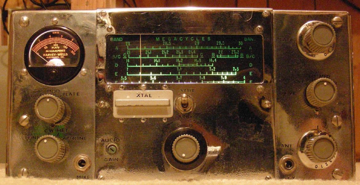
This project involves the restoration of a Harvey Wells T-90 Amateur Radio transmitter. The T-90 was made around 1960 and is capable of transmitting AM voice and Morse Code (CW). Output power from this rig is between 25W and 50W, depending on the power supply voltage and the frequency band being used.
The goal of the project was to first get the transmitter running in its original configuration, then to adapt it to my Modular CW Transmitter Prototyping System. The Modular CW system allows a stable DDS VFO to be used as the frequency standard for the transmitter, it also adds fully automatic operation and QSK break-in capability to the T-90.
The Harvey Wells T-90 transmitter requires an external AC power supply (type APS-90) or equivalent. I used my Transmitter Power Supply V3 to supply the required voltages. These include 6.3VAC at 8A for the filaments, 300VDC for the tube high voltage supply and 650VDC for the final amplifier high voltage supply. A (nominal) 12VDC supply is also used for operating the T/R relay and keying circuitry.
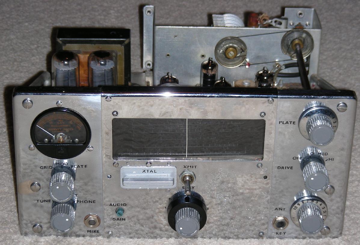
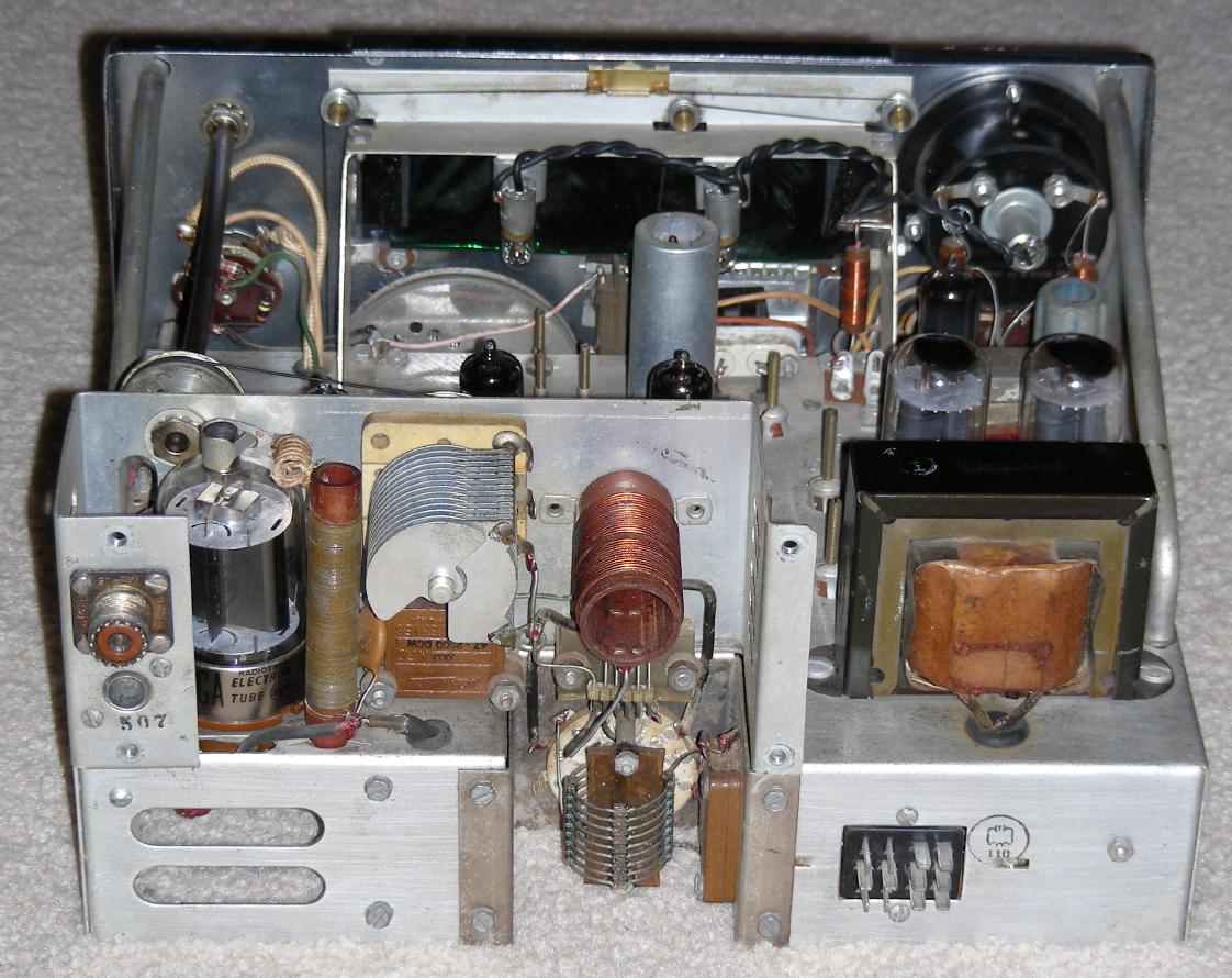
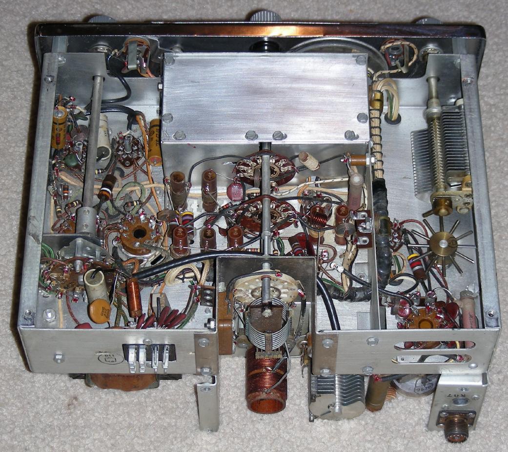
Note that the above interior photos were taken before some of the restoration work was done. The first step of the restoration involved carefully cleaning the chassis and parts with a toothbrush to remove dust and dirt. Be careful not to disturb any of the tuning coils that are on the bottom of the chassis, the fine wires in the coils are easily damaged.
All of the moving parts were cleaned and oiled with a lightweight lubricating oil. The switch contacts were all cleaned with de-oxit spray and all of the mechanical parts were operated back and forth to assure smooth operation.
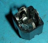
There were a few problems with this transmitter, the T/R relay had a missing armature and the T/R switch on the front panel had been replaced with a part that was too large so that it displaced the front panel glass. Both of these parts were replaced. The wiring in the AM preamplifier section had been modified, it was brought back to the original design. One of the pilot light sockets had a broken lead that required reconnecting. One of the 6AV5 modulator tubes tested very weak and was replaced with a better tube.
The two electrolytic capacitors in the T-90 audio preamp were replaced with new parts, old electrolytic capacitors are often out of spec or defective and should generally be replaced before they create further problems. Luckily, all of the power supply capacitors are external to this unit. The two 0.002uF DC blocking capacitors in the audio preamplifier circuit were replaced with 0.02uF parts, this optional change improves the bass response of the transmitter.
The resistors were checked for the proper value, all of the out-of-tolerance resistors were replaced. The old resistors were clipped off at the body and the remaining leads were formed into solder loops, this allowed the new resistors to be connected to the old lead loops without disturbing the original wiring and possibly breaking brittle tube socket pins.
The VHF parasitic supression coil on the plate of the 6146 was modified to include a parallel 15 ohm, 1W resistor in the middle of the coil. This is a standard method of lowering the coil Q to reduce harmonic radiation.
The T-90 was aligned according to the instructions in the manual, all of the coils were very close to the correct settings. The internal VFO was found to be unstable. The problem was tracked down to loose pins on the front panel crystal socket jumper. The pins were cleaned and the socket was re-sprung. A foam piece was attached to the crystal socket cover to keep the jumper from moving around. That completed the initial restoration phase of the project.
In its original configuration, the T-90 transmitter had a serious defect. If no microphone was plugged in and the function switch was changed from CW to AM, a loud feedback signal would be transmitted and arcing could be heard on the switch. Self-destruction of the function switch was sure to follow. Fixing this problem was fairly easy, the 3 pin 1/4" microphone jack was replaced with jack that has a built-in switch on the ring (middle) connector. The switch pin on the jack was grounded, see the above photo. This effectively grounds the mic input when nothing is plugged in. The jack was a part with the marking "JCC 3" from my junk box, it is a rectangular black plastic unit with a standard threaded mount.
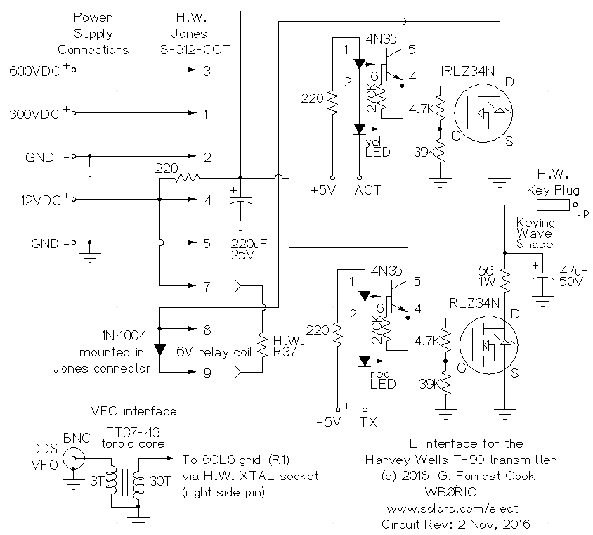
The interface circuit has to translate two TTL-level digital signals to the transmitter, the Active line and the Morse code Keying line. Both of the digital signals are active low (inverted). The interface uses two nearly identical optically-isolated MOSFET transistor switches. Note that the IRLZ34N MOSFET transistors shown in the schematic have "logic level" gates, I used these parts because I had a lot of them in stock. Normal gate IRFZ34N MOSFETs, or other N-channel devices should work fine here. The TTL control lines drive the 4N35 opto-isolators and use series LEDs for visual indication. The LEDs also insure that the 4N35 LEDs are fully turned off in the idle state since a TTL high output is around 4V, which can cause the 4N35 to turn on slightly.
The 4N35 output transistors switch a filtered 12VDC supply line to control the gates of the two MOSFET transistors. The Transmitter Keying MOSFET drives the T-90 cathode keying circuit through an R-C waveshaping network. This network reduces key clicks when transmitting. The Transmitter Active MOSFET drives the internal T/R relay in the T-90. Note that the T-90 is wired for 12VDC relay control using its internal series resistor and the internal 6V relay. A 1N4004 snubber diode is added inside of the 12 pin Jones-type power connector and is wired across the pins that connect to the 6V relay coil.
The DDS VFO interface uses a small toroidal RF transformer to step the 50 ohm impedance from the DDS up to the 5K ohm impedance of the T-90 oscillator's grid circuit. The DDS drive level is around 300mV P-P at 50 ohms. On the 80 meter setting, the DDS VFO should be set to output frequencies in the 3.5 to 4.0 Mhz range. On all of the other bands, the DDS VFO should be set to output frequencies at 7.0 Mhz and above. The DDS VFO frequency reading will need to be multiplied on bands which are multiples of 7 Mhz, this may be done automatically by the DDS VFO software.
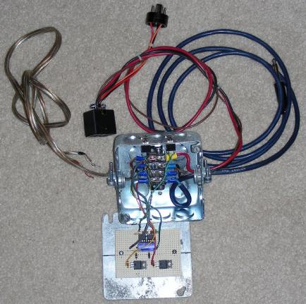
The interface circuitry was built external to the transmitter so that the T-90 could be left unmodified. Most of the circuitry was housed in a standard 4"x4" electrical utility box, Romex cable clamps were used to secure the wiring to the box. A piece of perforated circuit board was attached to the box lid using metal stand-off hardware All of the circuitry was wired on the board using point-to-point wiring. A 4 pin screw terminal was mounted on the bottom of the box, it connects to the 12.6VDC accessory power supply and the two control lines.
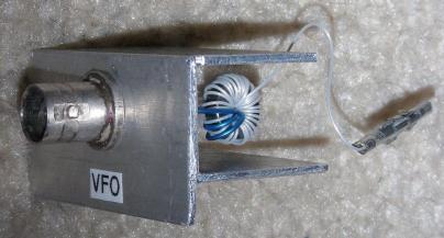
The DDS VFO interface was installed in an aluminum plug-in housing that fits into the T-90 XTAL cover plate hole. The connection to the oscillator grid circuit was made with a molex pin that fits into the right side hole on the XTAL socket. The housing was made with two pieces of aluminum L stock that were held together by a panel-mount BNC jack.
The transmitter may be used in its original configuration, according to the instructions in the manual. When using the transmitter in AM phone mode, the original microphone PTT scheme is used, this mode can coexist with the CW QSK interface. Using the transmitter with the automatic QSK system is much easier than with the manual T/R switch since the operation is controlled by the keyer. There is no need to flip the T/R switch before and after every transmission and the switched DDS VFO allows reception between the Morse dots and dashes. I have paired this transmitter up with my Drake 2B receiver and have made many Ham contacts with the setup.
Back to FC's Ham Radio Circuits page.