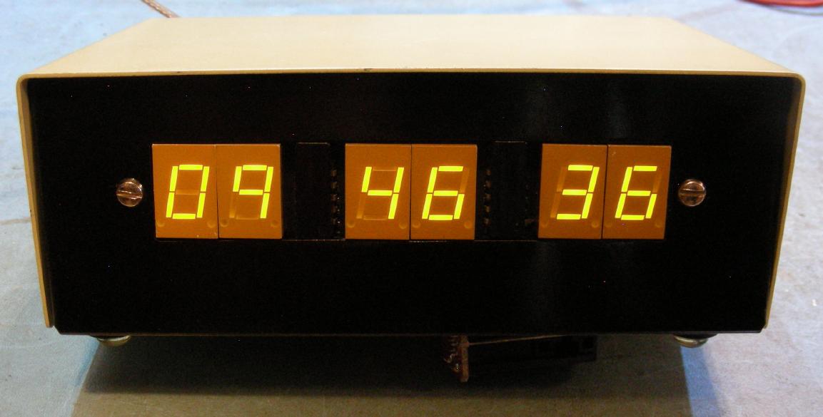
Front view of the MM5315N 24 hour clock
(C) 2021, G. Forrest Cook W0RIO
Front view of the MM5315N 24 hour clock
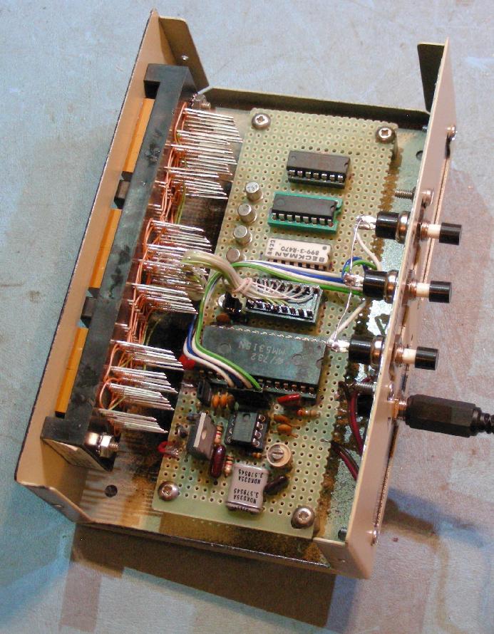
Inside view of the MM5315N 24 hour clock
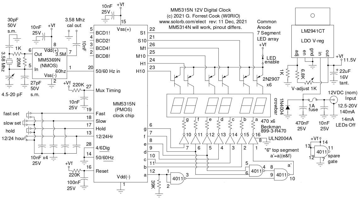
Schematic of the MM5315N 24 hour clock
This project involves the construction of a mid 1970's era digital clock that runs on 12VDC power. The clock is intended to be used for portable ham radio operation, it can also serve as a general purpose clock. Inexpensive digital clocks can be purchased for less than $10 and smart phones can provide accurate time info, this project is about having fun playing with old technology. An effort was made to use all of the features of of the clock chip and make a clock that will work well in ham radio operations with radio frequency (RF) emissions.
The heart of the clock circuit is a National Semiconductor MM5315N clock chip. That chip was chosen because your author had six of them in storage. A more common MM5314N clock chip could also be used if the different pinouts are accounted for. The MM5315N comes in a 28 pin DIP package and has multiplexed Binary Coded Decimal (BCD) outputs, which are not used in this circuit. The MM5314N is essentially the same chip in a 24 pin DIP package without the BCD outputs.
The clock features an internal time base that uses a 3.58 Mhz crystal and an MM5369N time base IC. The DC power is regulated with an LM2941CT low dropout (LDO) regulator IC which improves the timebase and LED brightnes stability. A LED enable switch is included to allow the clock to run at lower power levels, which can be handy for battery-operated use.
Extra logic was included to add the top 'a' segment to the LEDs when the number 6 is displayed, your author prefers display of the number 9 without the bottom segment so no additional logic was needed. Manual controls include buttons for Fast Set, Slow Set and Hold and there is an internal jumper to select 12 or 24 hour clock mode. The clock chip is wired to automatically reset to 00:00:00 when power is supplied.
The MM5369N time base IC uses a 3.58 Mhz crystal oscillator circuit and an internal divider to produce a 60 Hz reference signal that drives the MM5315N clock IC. The MM5369N also has a buffered oscillator output that is used for calibration of the crystal frequency. A trimmer capacitor is used to adjust the frequency of the crystal oscillator.
The MM5315N clock chip contains most of the circuitry for the clock and produces multiplexed output signals for driving the LED array. Note that the MM5315N is a PMOS IC so the Vss pin is positive and the Vdd pin is negative. The MM5369N chip is NMOS so the Vss pin is negative and the Vdd pin is positive. The RC components on the Mux Timing pin sets the rate of the LED multiplex circuitry and the RC components on the Reset pin insure that the clock powers on in the 00:00:00 state. The pushbutton and 12/24 Hour inputs are bypassed with 10nF capacitors for de-bouncing and RF immunity.
The six digit select pins are buffered and inverted using 2N2907 PNP transistors, 2N3906 transistors will also work here. No current limiting resistors are used for the PNP base connections, those are supplied internallhy by the clock chip. The 7 segment output pins are buffered and inverted with a ULN2004A darlington array IC, segment outputs are current limited with seven 470 ohm resistors in a resistor array IC. Regular 1/4W resistors can also be used here.
The logic that turns on the 'a' segments for the number 6 is provided by the 4011 CMOS quad NAND gate. The gate is wired to produce the equation a' = a or (e and f). The input from the a signal to the 4011 pins 1 and 2 has to be pulled down via a 39K resistor in order for the signal to properly drive the CMOS gate.
The LDO regulator IC circuit was copied from the LM2941CT data sheet, it is set up to provide a small adjustable voltage range. The 1N4004 diode works with the 1A fuse as a crowbar circuit. if reverse voltage is applied to the clock, the fuse will blow and the circuitry will be protected.
The clock circuit was built into an old A/B printer share box that happened to be the perfect size to hold all of the components. A rectangular hole on the front of the box was cut out with a nibbling tool in order to mount the LED display board. An aluminum plate was cut to fit into the existing holes in the rear of the box, holes were drilled in the plat to hold the pushbuttons, mounting holes and DC power connector. The front of the box was lightly sanded and spray painted with gloss black paint.
The display assembly was built on a junk-box wire-wrap display mounting board. Yellow Hewlett Packard 5082-7660 7-segment common-anode LEDs were plugged into the display board. The A through G segments of the six 7-segment LED displays were wired in parallel on the display board. The segments and individual LED anodes were brought out to a 16 pin DIP header which plugs into the main clock board. The LED array wiring was tested using a 5V supply and a 330 ohm series resistor to verify the correct wiring of the multiplexed display. A pre-fabricated 6 digit common anode LED display could be substituted here.
The clock board was hand-wired on a blank perforated circuit board using soldered wire-wrap wire connections. The components were placed in a manner that keeps the connections short and inline wherever possible. SIP pins were placed on the board for connections to the external switches via mating SIP headers. Solder points made with loops of tinned hookup wire were added to the edges of the board for connection to the DC power supply and the 3.58 Mhz calibration output. The clock board was mounted to the bottom of the case using 4-40 machine screws and threaded spacers.
The LDO voltage regulator will keep a regulated output voltage steady with an input voltage that is between 0.5V and 1.0V above the output. The regulator should be adjusted to approximately 11.5V, or slightly lower depending on the voltage range of the power source.
To adjust the MM5369N time base IC, connect a frequency counter to the 3.58 Mhz cal out pins and adjust the trimmer capacitor so that the crystal oscillates somewhere near 3.579545 Mhz. This adjustment should be made when the clock is at normal operating temperature and the input voltage is above the voltage regulator's point of regulation, typically around 12.5V or higher. With a quick first-try calibration, the clock was able to stay synchronized with the WWV time broadcast with less than 1 second of drift after 24 hours.
Tune in the WWV time signal on a short wave receiver or use a cell phone as a time reference. Power the clock on when the reference time reaches 0 seconds. press the fast and slow set buttons until the clock reads the same time as the reference. The hold button can be used to sync the time even closer to the reference.
To save power in battery-operated setups, turn the LED enable switch off when the clock is not needed, the clock will continue to keep time.
Back to FC's Ham Radio Circuits page.