(C) 2017, G. Forrest Cook W0RIO (formerly WB0RIO)
|
|
|

|
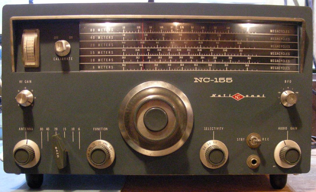
This project involves the restoration of a National NC-155 Amateur Radio receiver that was purchased at an estate sale. The receiver was made in the early 1960s and covers the 80, 40, 20, 15, 10 and 6 meter ham bands. The NC-155 is a nice looking rig with its "cosmic blue" paint, large and heavy tuning knob and well lighted tuning dial.
Unfortunately, this receiver suffers from mechanical instabilities in all bands above 80 Meters. This is mainly due to the use of increasingly higher frequencies in the main variable frequency oscillator and a number of mechanically unstable components. This article describes a number of fixes that can be done to greatly improve the stability, operation, power efficiency and safety of this receiver. Note that with the exception of the new bottom plate bracket, the modifications were done without drilling any holes in the receiver.
The first step in the restoration process was to download the manual from the BAMA site. The schematic was printed to several pages and the pages were cut and taped together to make a single large version. The receiver alignment instructions were also printed for easy access.
The bottom plate was missing from the radio, a new plate was fashioned by cutting and drilling a piece of aluminum stock. A circular saw with a composite metal-cutting blade was used to cut the new plate. The original plate had a bend on the back side. I do not have access to a metal brake, so I improvised and built a small bracket for connecting the bottom plate to the center of the radio's back panel. Four rubber feet were attached to the new bottom plate to prevent the receiver from scratching the surface that it rests on.
The next stage of restoration involved a thorough cleaning. The cabinet was disassembled and all of the components were dusted with an air sprayer. A wire brush was used to scrape off the rust and oxidation that had accumulated on the various metal surfaces. The cabinet and front panel were washed with a light soap and polished. All of the knobs were removed and cleaned with a soapy toothbrush. The glass dial was carefully cleaned in place using soapy Q-tips and the residue was soaked up with paper towels.
While the knobs were off, a light oil was applied to all of the control bearings. Oil was also applied to the switch bearings and tuning mechanism pullies. All of the switch and variable capacitor contacts were cleaned with CAIG de-oxit spray The potentiometers were sprayed with CAIG fader lube and rotated to spread the spray around. All of the excess oil and spray residues were soaked up with paper towels.
The vacuum tubes were carefully removed and cleaned with a light soapy solution, then rinsed and dried before re-inserting. Note that some of the tube brand names may wash off in the soapy water. This is a good time to test the tubes if you have access to a tube checker.
The two wire AC cord was removed and replaced with a 3 wire cord, the green wire was attached to the chassis with a solder lug. This is an important modification that can prevent the chassis from becoming an electrically "hot" shock hazard.
The 5Y3 rectifier was removed and replaced with a pair of 1N4004 diodes which were soldered to the bottom of the rectifier tube socket. A 470 ohm/10W resistor was added in series with the B+ line to compensate for the more efficient diodes and bring the B+ down to the correct voltage. The 5V rectifier filament winding was clipped off of the rectifier tube socket. It is OK to leave the 5Y3 tube in its sockets to maintain the original look of the receiver. It is a good idea to place 1nF/1KV ceramic disk capacitors across the 1N4004 diodes for transient protection.
AC line voltages in the 1960s were typically around 115V and are now usually 120V or more. The now-unused 5V rectifier filament winding (yellow wires) on the power transformer was re-routed so that it is now in series with the transformer's primary winding (black wires) so that it acts as a buck winding. This change brought the filament voltage down from 7V to 6.5V. If the filament voltage goes up to 7.5V, the rectifier windings should be swapped. An alternate approach would be to power the rig using an external 6.3VAC filament transformer wired as a buck-mode autotransformer.
In the original configuration, the power transformer became very hot when running on the 122VAC line voltage at my location. With the solid-state rectifiers, no 5Y3 filament and the 5V winding wired to buck the line voltage, power consumption dropped from 88W to 65W and the transformer now only gets slightly warm after extended operation.
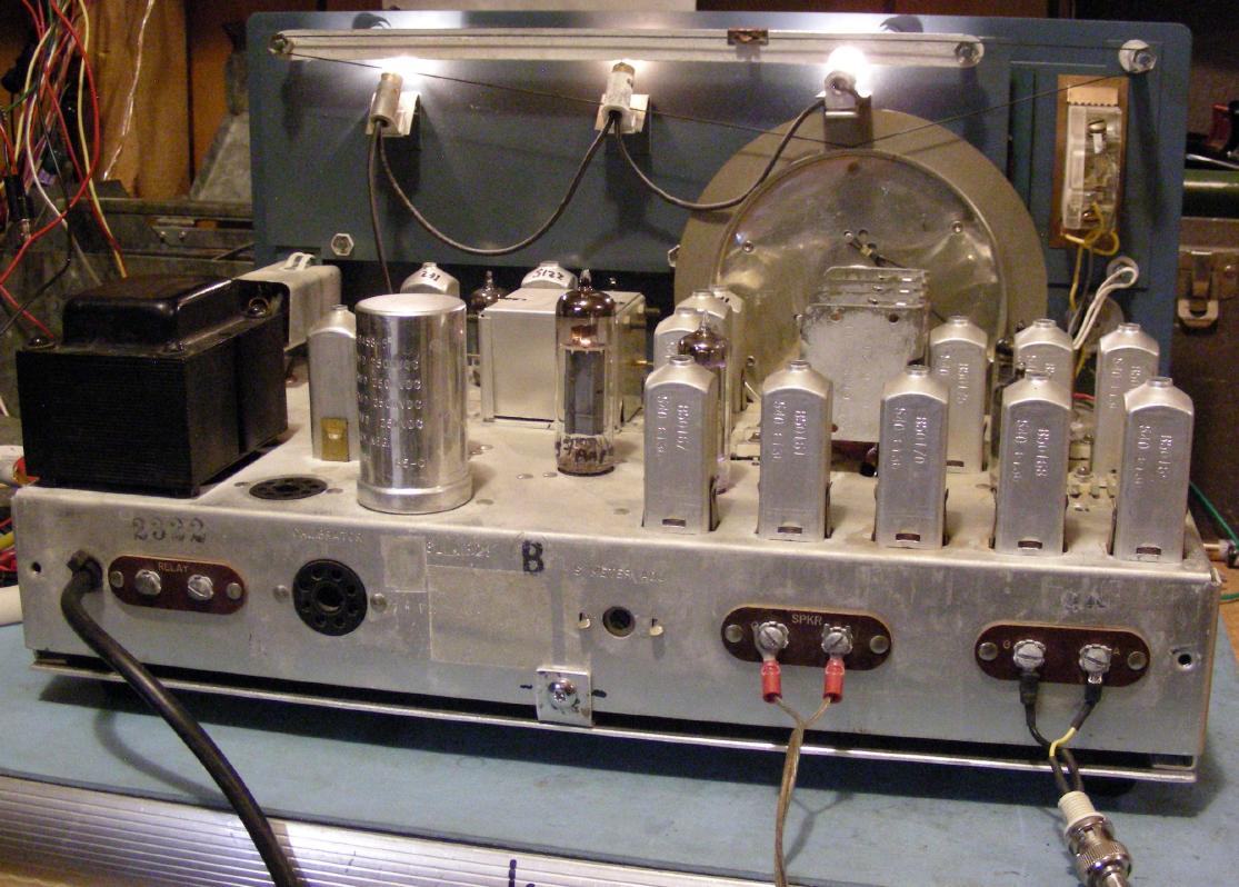
The receiver has four electrolytic capacitors in one metal can. All four capacitors were disconnected and replaced with similarly rated modern capacitors. The original capacitor was left in place to preserve the look of the receiver. All of the chassis screws were tightened, especially those which held down solder lugs.
The high wattage and low value resistors were all checked. The 2.2K VR tube bias resistor was found to be out of tolerance and was replaced. That fixed a problem where the VR tube would occasionally stop glowing and the received frequency would drift. A few cold solder joints were repaired and numerous long wire ends were clipped short at various solder terminals. Excess solder flux was scraped off of various locations under the chassis using a dental scraping tool.
The radio was calibrated according to the instructions in the manual. The calibration instructions were somewhat confusing, but were good enough to allow me to adapt my own procedures. A black sharpie pen was used to mark which bands each of the tuneable coils and trimmer capacitors are associated with. A calibrated and stable frequency generator is necessary for making an accurate receiver calibration. The 230 Khz IF resonators were very close to their specified frequency and were difficult to adjust so they were left alone.
The radio was now working well enough to connect to an antenna and scan around the ham bands. Some serious stability issues were noticed, especially on the 20, 15, 10 and 6 meter bands.
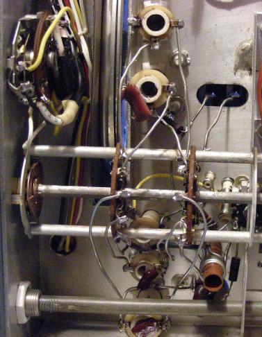
I started poking around the underside of the oscillator section with a plastic screwdriver tip while listening to a fixed carrier from the signal generator. I found a number of obvious mechanical issues that affected the stability. The capacitors across each of the oscillator coils had long and floppy leads, these were pinched down to smaller sizes and solder was used to fill the pinches. This was much easier and safer to do compared to removing the caps and re-soldering the leads.
The wires between the band switch and the various oscillator coils were shortened and carefully spaced away from the chassis and other wires. One of the longer tuning capacitor wires was braced to a chassis-mounted ground lug with a 10M 1/2W resistor. The resistor is too high in value for the circuit to "see", but it stabilizes the wire from any movement. These changes can be seen in the bottom left photograph.
The oscillator capacitors were bent over the back of their associated coils and were secured to the coils using a hot glue gun. The coils were secured to the chassis on the top and bottom side with more hot glue. A soldering iron was used to further melt the hot glue and spread it around the coil bases and the chassis. Small chunks of candle wax were melted into the tops and bottoms of the oscillator coils to stabilize the tuning slugs.
The two capacitors that resonate the converter tube oscillator between the 1st and 2nd IF (C28, C31) were also mechanically unstable. I shortened the leads, moved the nearby wiring away from the capacitors and hot-glued the capacitors together.
The capacitor on the back of the BFO coil was touch sensitive. I improved the BFO stability by securing the capacitor to the back of the BFO coil with a dab of hot-melt glue.
The receiver was again tested on the air and found to be much more stable than before. It was now workable on 80 through 10 meters with stability gradually decreasing on the higher bands. The 6 meter band is still quite mechanically unstable due to the high oscillator frequency and the mechanics of the band switch, oscillator coil and associated trimmer.
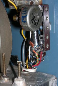
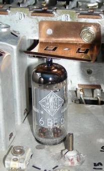
The 6BE6 oscillator tube was a bit loose in its socket, the frequency would move if the receiver was tapped on the side. A tube spring-clip was fashioned out of springy metal and that was attached to a hole in the main tuning capacitor using a self-tapping screw. The clamp can be seen in the lower right photograph. The clamp greatly improved the stability of the oscillator.
The one remaining mechanical stability issue is with the band switch, which can change the frequency when it is wiggled. This is not a huge problem as long as the switch is wiggled into a stable position after changing bands. After all of the mechanical stability improvements had been made, the receiver was calibrated one last time.
The RF Gain control made a lot of scratchy noise in the receiver's audio when it was adjusted. I cleaned the pot a second time with fader lube, then tried substituting several other 10K potentiometers but the problem persisted. I found that putting a 2.2uF, 35V capacitor in parallel with a 10nF disc capacitor between ground and the "hot" side of the potentiometer was sufficient to eliminat the noise.
When connecting the NC-155 receiver up with a companion transmitter, it was necessary to manually turn down the RF gain control before transmitting. If this was not done, an extremely loud audio signal would come out of the receiver. The loud signal also de-tuned the receiver, making it difficult to monitor the transmitter signal.
A simple receiver mute circuit was made using a SPDT 5V reed relay and a 10K trimmer potentiometer in series with a 6.8K fixed resistor. A DC control signal from the transmitter causes the relay to switch between the front-panel RF gain control (receive) and the internal trimmer (transmit). The relay circuit was built onto a 4 pin solder post, which was mounted on an existing front panel screw. The relay coil wires were routed to two unused pins (1 and 2) on the octal calibrator socket using a twisted pair of wires. Two 10nF bypass capacitors were connected between the twisted pair wires and ground at the octal socket to keep stray RF out of the receiver. This modification can be seen in the bottom center photograph. The receiver now automatically reduces its gain and produces a nice-sounding sidetone when the transmitter is operating.
After all of the above modifications, The NC-155 receiver is much more useful for actual on-the-air communications and is quite stable on the 80 through 20 meter bands after sufficient warm-up time. This restoration project illustrated the value of detailed vibration testing while listening to stable signals produced by a frequency generator. The stability of the modified receiver is much better than it could have ever been when it was new. The receiver is now more power efficient and the risk of shock from a hot chassis has been eliminated, assuming it is plugged into a correctly wired outlet.
NC-155 Manual (pdf)
Back to FC's Ham Radio Circuits page.