(C) 2009, G. Forrest Cook
Antique transistor and tube AM/short wave radios can be fun restoration projects. It is usually necessary to re-align the receiver's local oscillator so that the tuning dial shows the correct frequency. This circuit can produce amplitude modulated (AM) tones on various frequencies that these receivers typically pick up. This circuit can also be used as a low-power transmitter for use in tracing the AC wiring in a building.
The oscillator module can often be salvaged from discarded computer devices, good sources are old PC motherboards, ethernet cards, video cards and disk drives. New oscillators are also readily available.
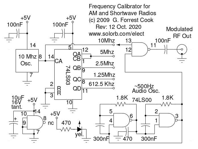
The oscillator block is a self-contained device that runs on a 5V DC power source and produces a fixed-frequency square wave signal. This is used as the master clock oscillator and produces the highest frequency for the generator. The master clock is fed to a 74LS93 divide by 16 counter IC which produces sub-frequencies at 1/2, 1/4, 1/8 and 1/16 of the master clock frequency.
The audio oscillator uses two sections of a 74LS00 wired with a feedback loop to produce an approximately 500 hz square wave. Note that the 470pF capacitor across output pin 6 helps to load the oscillator lightly for removal of RF components and frequency stabilization. This signal is NANDed with one of the five HF signals to produce an AM modulated waveform. The modulation involves a simple on/off switching of the carrier wave at the audio frequency, it is simple but effective for the task at hand.
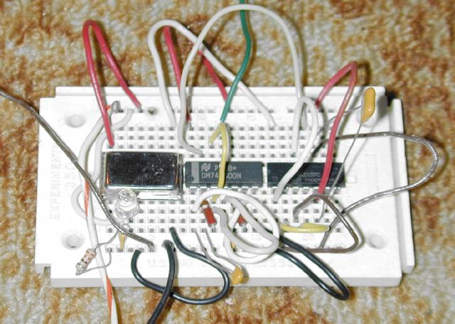
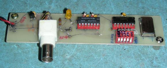
The circuit was originally built on a hand-wired prototype board as shown in the top photo. A more permanent circuit was then built on a scrap piece of unused circuit board which had a few DIP socket patterns. Holes were drilled in the board for the oscillator module and BNC output jack. Most of the original traces were removed and the circuit was wired with tinned copper wire and teflon insulation. A 78L05 5V regulator was added to the circuit board to allow the circuit to be powered by a 12V supply.
IC sockets are recommended for the chips is you solder the circuit together. Selection of the available frequencies can be done with an optional 1P5T rotary switch or a board-mounted 5 position DIP switch. In the solderless prototype board shown above, frequency selection is done by moving a jumper wire.
The 5VDC supply is provided by an external regulated DC power supply, four 1.25 NiMH cells could also be used. If you use NiMH cells, don't forget to add a fuse and a switch. It is a good idea to build the circuit into a small metal box, use insulated standoffs and machine screws to mount the board to the box.
Apply power to the circuit and select an appropriate output frequency. by connecting Jse a test lead to place the Modulated RF Out signal near the receiver's antenna input. Direct connection to the receiver's antenna input is usually not required and may overload the receiver.
Set the receiver to the desired band and tune around until you hear the 500 hz audio tone. If you are unsure if the tone is coming from the calibrator, power the calibrator off and see if the tone disappears. Adjust the receiver's oscillator trimmer, which is usually located on side of the main tuning capacitor until the tuning dial reads the correct frequency. Repeat this procedure for all bands by selecting the appropriate calibrator output frequency.
The calibrator generates a signal that is wide in harmonic content since the RF is modulated by a square wave audio signal. This may result in multiple signals showing up on the receiver's dial, the problem may be worse on inexpensive radios that suffer from imaging problems. The best way around the issue is to decrease the coupling between the calibrator and the radio to a point where the signal is fairly weak. If multiple signals still persist, tune the radio to the strongest signal.
When using the calibrator for tracing building AC wiring, power the calibrator via a small 5V AC-operated supply and connect a short antenna to the calibrator's output. Plug everything into a remote outlet and go to the building's circuit breaker panel with a battery-powered short wave radio. Tune in the signal and turn off the breakers until the signal goes away. Make a list of which breaker controls the various outlets. Keep in mind that some power supplies may keep the calibrator running for a a few seconds after power is removed while the capacitors discharge.
An easy way to double the number of output frequencies from this circuit would be to add an 8 Mhz oscillator and switch the 74LS93 input between 10Mhz and 8Mhz. This would add the following output frequencies: 8Mhz, 4Mhz, 2Mhz, 1Mhz and 500Khz.
The output of this circuit is an RF square wave modulated by an audio square wave, it is rich in RF harmonics and wide band across the chosen output frequency. An RF sine wave output would be better for many applications. The RF spectrum can be cleaned up by adding a parallel-resonant coil/capacitor tuned circuit across the output.
One resonant circuit would be required for each output frequency and those could be selected with a multi-pole switch. A low-impedance output could be produced by adding a few turns of wire around each inductor. Adding tuned circuits would greatly increase the a number of components used and make the circuit a lot more complicated to build.
Back to FC's Test Equipment Circuits page.