(C) 2014, G. Forrest Cook
This project uses a "magic eye" indicator tube as the meter element of a general purpose wavemeter. The wavemeter can be used to monitor the actual radiated power from a ham radio station. This can be very helpful when adjusting an antenna tuner. The wavemeter can also be used as an audio level indicator (vu meter). The project can provide some nice "eye candy" for your ham radio shack or hi-fi audio setup.
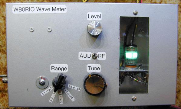
The wavemeter covers five different frequency ranges spanning 3.1 Mhz to 33 Mhz, covering the 80 Meter through 10 Meter amateur radio bands. A switching arrangement is used for selecting different coils, coil taps and capacitance ranges for the various frequency spans. A 3P5T range switch was used since I had it in my parts collection. A 3P3T switch could cover the same frequency range. The second and fourth ranges provide finer tuning, but are redundant.
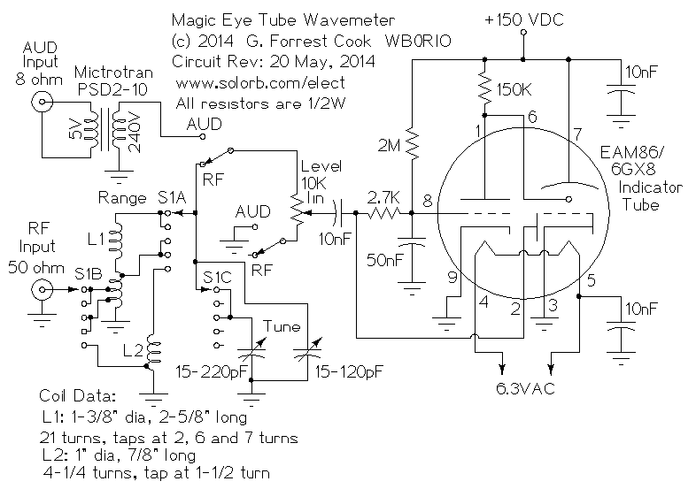
The EAM86/6GX8 tube is a fairly rare tube but it can usually be found on eBay. This circuit could be built with any of the more common magic eye tubes. Tubes such as the EM80/6BR5, the EM84/6FG6 and the EM87/6HU6 should work just as well with appropriate pin changes. See my list of Fluorescent Magic Eye Tubes for alternate tube ideas. The EAM86/6GX8 is unusual because it includes an internal diode (pin 2). If you use a different indicator tube, just substitute a standard silicon diode such as a 1N4148 for the EAM86/6GX8 diode element. The diode's cathode (stripe) goes to ground. If you prefer to use a vacuum tube diode, one section of a 6AL5 should work nicely.
Power for the circuit is provided by my Power Supply for Vacuum Tube Experiments set for 160V. Most older vacuum tube receivers include an accessory power output that can be used to power this circuit. If the available B+ supply is higher than 160V, it will be necessary to change the value of the three bias resistors or use a B+ dropping resistor and an electrolytic filter capacitor to produce around 150V-160V.
A good way to receive a sample of your transmitted signal is to use a short dipole or loop antenna on the end of a length of coaxial cable. The pickup antenna should be mounted a few tens of feet from your main antenna and as far from your feedline as possible. If your main antenna is some form of dipole, the pickup antenna should be oriented parallel to the main antenna, this will allow it to pick up the actual transmit signal and not any feedline radiation. A physically short, but resonant antenna would make an ideal pickup antenna, but it would mostly be useful on its resonant frequency or on odd harmonics of that frequency.
This project involves the use of potentially lethal high voltages including 120 VAC and 160 VDC. The project should only be taken on by someone who has experience working with high voltage circuitry. The power cord should always be removed and the power supply capacitors should be discharged when working on the wavemeter.
The AUD/RF switch allows the wavemeter to monitor an audio line or an RF line. The Aud input is routed through a filament transformer, this matches the low impedance of a speaker output to the higher impedance of the detector circuit. The RF input is fed to a tap on the coil of a parallel resonant LC circuit. The coil tap transforms the low impedance RF input to the higher impedance of the detector circuit. The sensitivity control adjusts the amount of signal going to the detector circuit. The second half of the AUD/RF switch grounds the lower end of the level control for audio measurements. For RF measurements, the level control is wired as a series variable resistor, this arrangement gives the circuit higher sensitivity.
The range switch is used to select different coils and coil taps for the various frequency ranges. The range switch also adds the larger section of the dual tuning capacitor across the input coil in two of the lower frequency ranges. The frequency ranges are overlapping and somewhat redundant, the switch that was used had extra positions and this allowed for finer tuning on some of the ranges. A three position switch should be sufficient to cover the entire frequency range.
When the coil and capacitor are tuned to the frequency of the monitored signal, RF energy will feed through the sensitivity control into the tube's diode circuit where it will be rectified into a negative going bias voltage. The 50nf grid capacitor integrates the rectified RF or AF to provide a more slowly changing DC bias signal. As the signal level rises and the bias voltage goes more negative, the display tube's bars will become wider until they cross in the center.
There are three bias resistors on the EAM86/6GX8. The 150K resistor limits the plate current for the tube's triode section. The 2M resistor is used to turn the glowing bars on the indicator tube almost off (open) when there is no input signal. The 2.7K resistor sets the bias level for the triode and internal diode.
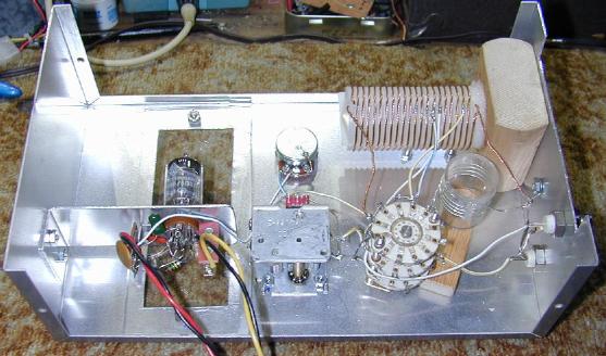
The wavemeter was built into a previously used 6"x10"x3.5" utility aluminum box. a hole was cut into the front of the box and a clear plexiglass window was mounted in the hole. The indicator tube's socket was mounted on a bracket so that the tube is visible through the hole. The variable capacitor, range switch, AUD/RF switch and level control were all mounted on the front of the box. Two BNC input connectors were mounted on the side of the box and the filament and B+/ground wires were routed out of the back of the box for connection to an external power supply.
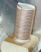
Two coil forms were made, one (L1) for the first four ranges and a smaller one (L2) for the highest frequency range. L1 was wound on a 1-3/8" diameter nylon lawn sprinkler filter and L2 was wound on a 1" diameter plastic cap. Both coils were attached to wood blocks using a hot glue gun, the blocks keep the coils away from the metal box. Two lines of hot glue were placed across L2 to keep the wire from moving around. The tuning capacitor is a dual-section part that was scrounged from a 1960s vintage AM radio receiver.
A well-stocked junk box is the first place to start, your author scrounged most of the parts for this project from discarded electronics. The indicator tube and socket can be found on eBay or from outlets such as Antique Electronic Supply.
The only adjustment that the circuit requires is choosing resonant L/C values and associated coil taps for each range of frequencies that the circuit is used on. The larger coil is used for four frequency ranges and the smaller coil is used for the fifth range. The range switch is wired to select the resonating tap and coupling tap for a particular frequency range.
To find the best coil tap positions, select a range and adjust the variable capacitor to its center position. Apply RF to the RF input and adjust the frequency for the maximum reading on the display tube. When building the wavemeter, it is possible to move the input coil tap up and down the coil. You should see an obvious peak in the indicator tube's display when the best impedance match is found. Solder a tap wire to that point. The best tap point for a 50 ohm line is typically 25-30% of the total coil turns used.
Connect the pickup antenna to the wavemeter and power up the circuit. Set the RF/AUD swich to RF and select the appropriate frequency range for the band you wish to monitor. Transmit a test signal and peak the variable capacitor for the highest indication on the tube. Adjust the sensitivity control for a mid-level reading. Adjust your antenna tuner for the maximum reading on the indicator tube. The highest transmit power may not necessarily coincide with the lowest SWR reading.
The wavemeter can also be used as an RF probe for testing RF circuitry. A few turns of wire on the end of a short coax line that is plugged into the RF input will work nicely for sniffing out RF in transmitter circuits.
For monitoring audio, connect the Audio input wires across a receiver's speaker lines and set the AUD/RF switch to AUD. Adjust the level control for a good indication on the display tube. The audio input is electrically isolated by the input transformer, so ground loops are not a problem. Many other audio devices such as stereos and guitar amps can be monitored with this device.
Back to FC's Ham Radio Circuits page.