(C) 2010, G. Forrest Cook
Prior to the 1950s, many rural areas in the US had no electricity. Many companies sold battery operated vacuum tube radios for use in these areas, the radios are commonly called Farm Radios. Farm radios are often available at very reasonable prices and can make a good restoration project.
One common type of farm radio used a large 1.5V battery cell for the tube filaments (the "A" battery) and a 90V battery for the plate supply, (the "B" battery). I have also written a V2 Farm Radio Power Supply article for radios that use a 6V filament voltage and a 135V B+ voltage. This can also be adapted for 2V filament voltages with a switch-mode voltage regulator.
The "B" battery is where the common use of the term B+ for a high voltage supply originated. The 90V batteries are no longer available and using a modern substitute would be both expensive and limited in operating time.
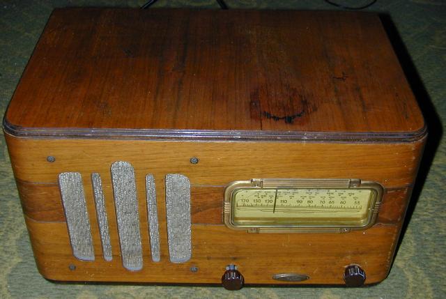
This project involves constructing a power supply that allows this type of radio to be operated from a modern 120VAC power line. The radio used for this project was made under the brand name Western Air Patrol by RCA/Hazeltine (no model number), it uses four 1.5V tubes. This project should be adaptable to other similar farm radio models by changing one resistor in the B+ circuit.
This device uses high voltages including 120VAC and up to 160VDC. The project should only be taken on by someone who has experience working with high voltage circuitry. When working on the radio, the power supply should be disconnected from the AC input and the B+ line should be temporarily shorted to ground to discharge the two electrolytic capacitors.
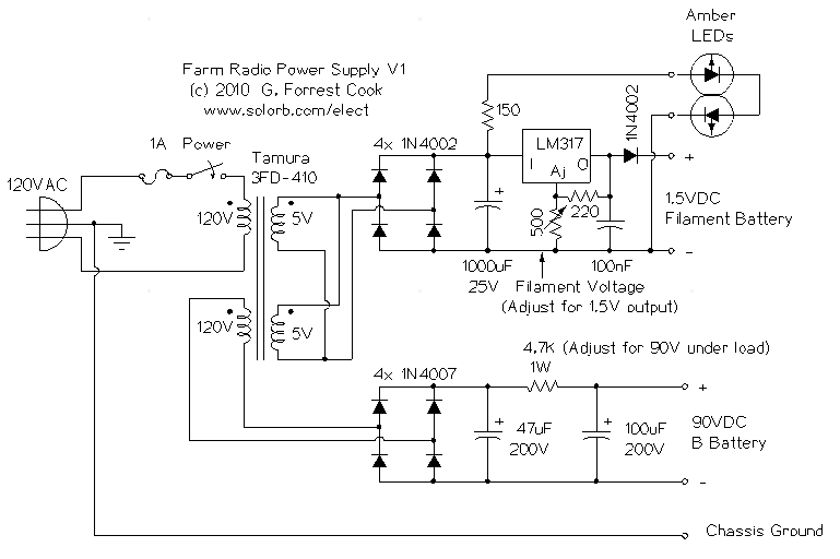
The heart of the power supply is a Tamura 3FD-410 5V dual primary/dual secondary transformer. These are available from DigiKey.com for reasonable prices. Normally, the transformer's primary windings would be connected in series for 240VAC operation or in parallel for 120VAC operation. This circuit takes one of the primaries and repurposes it as a 120VAC secondary. For this to work, the transformer should be somewhat over-rated, which it is in this case.
The two 5V secondary windings are combined in parallel and sent to a bridge rectifier and filter capacitor to produce around 7VDC. This DC voltage is current-limited by a 150 ohm resistor and used to drive two amber LEDs. The LEDs can be hot-glued to the inside of the radio above the dial to provide dial lighting and power-on indication.
The 7VDC is also sent to an LM317 adjustable voltage regulator IC. The LM317 normally produces a minimum voltage of 1.7V, which is too high for this application. A series 1N4002 diode is used to drop about .5V to produce a minimum voltage of 1.2V. The regulator is adjusted so that the filaments operate at 1.5VDC.
The 90VDC B+ supply uses a bridge rectifier across the transformer's second primary winding to produce around 160VDC. The rectified DC is filtered through a pair of electrolytic capacitors and a series resistor. The resistor and the current drawn by the tubes drops the B+ voltage to the required 90V.
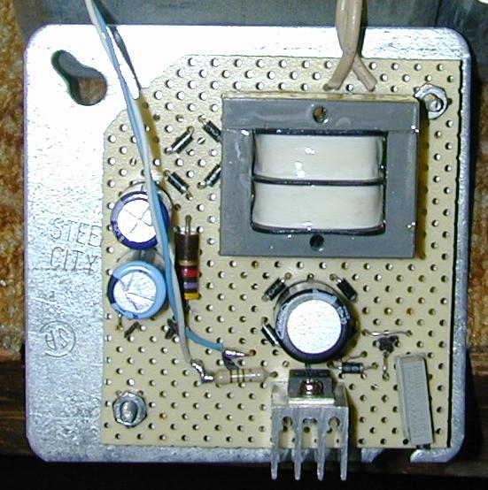
The power transformer and associated parts were mounted on a piece of perforated breadboard material, connections were soldered on the bottom of the board using point-to-point wiring. The LM317 regulator should be mounted on a small heat sink using heat sink grease. All external connections were brought out to small wire loops on top of the breadboard, the radio wiring can be soldered to these loops.
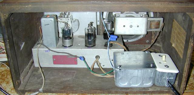
The power supply board was mounted to a standard 4"x4" electrical utility box cover using two 6-32 screws and 1/4" spacers. The switch and fuse were mounted in a separate 2"x4" electrical utility box, a standard light switch was used. The two boxes were joined together by knocking out adjacent holes on each box, the boxes were held together with an electrical box cable clamp. The power supply and switch assemblies were secured to the inside of the radio using a pair of wood screws. The power cable was secured to the switch box with a cable clamp.
Unfortunately, the original volume control pot in this radio was bad, so I used a substitute pot that had no switch and set up the external power switch as shown in the photos. In this radio, the original switch on the volume control had two circuits, one for the 1.5V battery and one for the 90V battery. The two DC circuits were unsoldered from the old switch and connected through like when the the switch was turned on.
If you have a working pot and switch on your radio, it should be possible to repurpose the radio's power switch for controlling the AC supply. The switched DC lines should be isolated from the switch and connected through as explained above, then The switch contacts can be extended with two wires that run into to the power supply box.
The filament voltage regulator should be set to the minimum value and then connected to the radio's filament circuit. The regulator should be adjusted up until the filament voltage reads 1.5VDC. The filaments in this radio's tubes produce a very faint glow compared to most tubes, you may only be able to see them in the dark.
The B+ supply voltage is adjustable by changing the value of the 4.7K 1W resistor. If the B+ is too high, use a resistor with a higher value, if it is too low, use a resistor with a smaller value.
Now is a good time to align the radio. The trimmers on the variable capacitor should be adjusted to set the dial frequency and antenna resonance, then the IF transormer adjustments should be tweaked for the loudest signal. For the best IF adjustment, move one adjustment clockwise a tiny amount and the other counter-clockwise a tiny amount. This produces a wider IF bandwidth.
After adjusting the filament supply, check to see that all of the tubes are lighting up, this may need to be done in a dark room. If one tube doesn't light up, it is probably bad. If all of the tubes are dark, there may be a wiring problem, a bad power switch or the filament line had too much voltage applied at some time in the past.
Once you have determined that all of the tubes light up, check to see that the B+ voltage is dropping down to around 90V. If the B+ stays around 160V, the radio is not sinking any current from the high voltage supply. This indicates that there may be problems with the wiring, the power switch or one or more of the tubes.
Turn on the power, tune in a station and enjoy. The radio shown uses a mere 2W of AC power to operate and it produces plenty of volume. An interesting feature of radios that use these low voltage tubes is that unlike most tube devices, they turn on almost immediately. This is because the tubes filaments are used as direct cathodes, producing a very fast warm-up time.
Another interesting feature of old battery-operated tube radios is that their internal parts tend to be in much better condition than their line-powered counterparts. This is due to the fact that farm radios run very cool and the components were never baked for long periods.
Back to FC's Ham Radio Circuits page.