(C) 2020, G. Forrest Cook
|
|
|
|
|
|
|
|
|
This is my second version farm radio power supply project. The Version 1 supply (recommended background reading) is suitable for powering battery-operated tube radios that run on 1.5 VDC for the filament and 90 VDC for the B+ supply. This supply can power tube radios that use 6.3 VDC/1A for the filament supply and 135 VDC/30mA for the B+ supply.
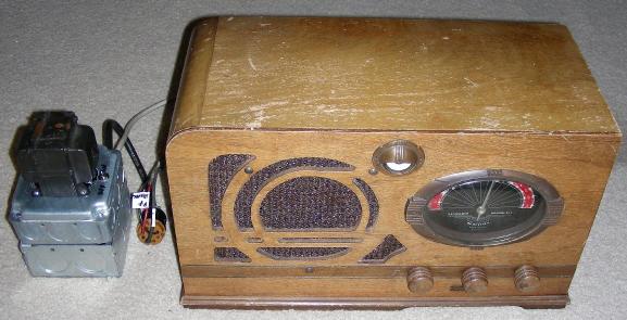
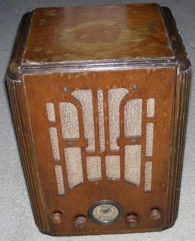
The supply was built so that it can power two (or more) different farm radios as well as other vacuum tube projects. The two radios that it powers are a Coronado model 504 table radio and a Crosley model 605 tombstone radio. The Coronado requires a +6 VDC filament supply and a +135 VDC B+ supply.
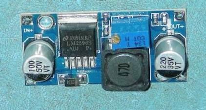
The Crosley requires a +2 VDC filament supply, a +135 VDC B+ supply, a -9 VDC bias supply and a -4.5 VDC bias supply. An inexpensive switch-mode voltage converter board that is based on the LM2956S IC is powered by the +9 VDC unregulated filament supply. The board produces the +2V filament voltage for the Crosley radio. The Crosley also uses the extra -9VDC bias voltage supply with a voltage divider to provide the -4.5 VDC voltage.
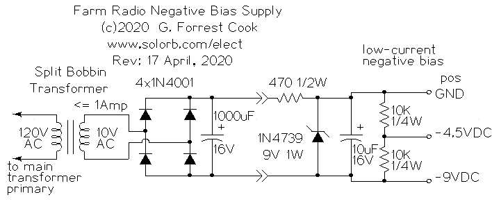
A low-current negative bias power supply schematic is also shown, it can provide a substitue for a single -9V C- battery or a tapped -9V/-4.5V C- battery. This is used for the Crosley radio.
This device uses high voltages including 120 VAC and up to 185 VDC. The project should only be taken on by someone who has experience working with high voltage circuitry. When working on the radio, the power supply should be disconnected from the AC input and the B+ line should be temporarily shorted to ground to discharge the two electrolytic capacitors.
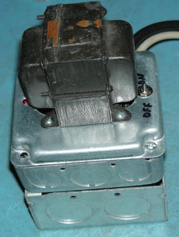
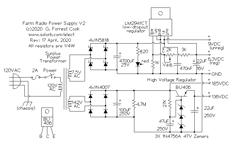
The heart of this power supply is a surplus vacuum tube transformer with a 142 VAC high voltage winding (unloaded) and a 7.5 VAC (nominally 6.3 VAC) filament winding. Similar transformers can often be found on eBay for reasonable prices. The filament winding should be rated at 1 Amp or greater and the high voltage winding should be rated at 135 to 150 VAC at 25mA or greater. The transformer power is switched by an SPST switch and a 2A fuse protects the supply against short circuits.
For the regulated 135 VDC B+ supply, the transformer's high voltage output is rectified by four 1N4007 diodes in a bridge configuration and filtered by a 100uF electrolytic capacitor to produce the 185 VDC unregulated high voltage output. A 4.7M bleeder resistor is used to safely discharge the capacitor when AC power is shut off.
The high voltage regulator circuit uses a string of three 47V zener diodes attached to the base of a BU406 NPN high voltage transistor. Many other transistors can be substituted as long as they are rated at 200V or greater. The 27K resistor is used for bias current to the BU406 transistor and the string of zener diodes. This is a fairly low level of bias for the zeners, which causes them to regulate at around 45V per diode. The 47uF capacitor across the zener diode stack decouples the zener noise from the BU406 base. On one farm radio, this capacitor also eliminated a motorboarding sound that could be heard with the volume turned low. The 22uF capacitor across the output stabilizes the regulated B+ line before it is sent to the farm radio. A larger value capacitor could be substituted.
For the regulated 6.3 VDC filament supply, the transformer's low voltage output is rectified by four 1N5818 Schottky diodes in a bridge configuration and filtered by a 4700uF electrolytic capacitor to produce the 9 VDC unregulated low voltage output. This output powers the red LED and can is also used for running an external switching voltage converter that produces a 2VDC filament voltage. The LM2941CT low-dropout regulator produces a regulated 6.3 VDC output at up to 1 Amp of current. The associated resistors and capacitors are used to adjust the LM2941CT output voltage and filter the input and output.
Note that a few tricks are used in the low voltage regulator to increase the margin of regulation. Unregulated filament voltages can cause output hum in farm radios. First, the transformer's output voltage is a bit higher than the nominal 6.3 VAC due to modern line voltages being 120 VAC instead of 110 VAC. Second, the Schottky diodes drop about 0.5V each under load compared to regular silicon diodes which drop of around 0.7V each under load. Third, the low-dropout regulator can produce regulated output with an input that is just above 0.5V above the output voltage. Finally, the large 4700uF capacitor keeps the ripple voltage of the unregulated 9 VDC line low under loads approaching 1A.
The primary winding of the bias supply power transformer is connected to the primary of the B+/Filament transformer in the upper schematic. The 10 VAC secondary winding drives a bridge rectifier, silicon diodes were used but Schottky diodes could be substituted for a slightly higher output voltage. The rectified DC is filtered by a 1000uF capacitor. The filtered DC supplies current to a 1N4739 9V zener diode through a 470 ohm current limiter. The zener provides a regulated -9 VDC, zener noise is filtered by the 10uF capacitor. The positive output of this supply is connected to ground, the negative 9V output goes to the radio. A voltage divider made with two 10K resistors provides a very low current -4.5V bias voltage which is required by the Crosley model 605 radio.
The power supply was built on a stack of two 4"x4" electrical utility boxes, the top box is an extender type with no bottom plate. The power transformer was mounted on a raised box cover over a hole that is sized for a standard duplex outlet. Four holes were drilled into the box cover for the trasformer mounting brackets. The transformer's wires fit nicely in the two outlet holes and the outlet mounting holes were drilled out to hold the power LED and the on/off switch. An L-shaped aluminum bracket was cut out and mounted under two of the transformer mounting bolts, it is used to hold two perforated circuit boards.
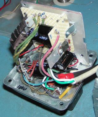
The majority of the rectifier and regulator circuitry was wired on a set of three perforated breadboard pieces, with wiring between the components done using point-to-point wiring. The high voltage bridge rectifier was assembled on one circuit board. The low voltage bridge rectifier and regulator was assembled on the second circuit board and the high voltage regulator was assembled on the third circuit board.
Point-to-point wiring was used to connect the various components on the perforated circuit boards and teflon insulation was used to cover the interconnecting wires. Push-in Vector Clips were used for making connections to the power power transformer secondary leads and the DC output leads.
The AC line input wire, fuse, switch and transformer primary wires were connected wired to a 3 pin terminal strip. The AC line and DC output wiring all pass through a standard Romex cable clamp on the side of the box, be sure to run the wires through the clamp before soldering. The DC output wires connect to an external shielded female octal tube socket, this allows several different radios to be plugged into the power supply.
The LM2941CT LDO regulator is attached to an aluminum heat sink using a 4-40 machine screw and nut, silicone grease was used between the regulator and the heat sink. The BU406 high voltage transistor is attached to another aluminum heat sink in a similar manner. Note that the BU406 heat sink is electrically live and should not come in contact with the chassis or any wiring.
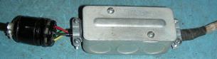
The negative bias supply was split into two parts, the transformer, bridge rectifier and filter capacitor were mounted in the main power supply box with the -11V output going to the octal output socket. The remaining zener diode, three resistors and capacitor were installed in a small utility junction box that terminates the Crosley radio's DC input cable. The small 3A DC to DC switching converter is also housed in the Crosley's junction box, it coverts the +9V unregulated filament voltage to +2.1V / 500mA for powering the Crosley's filaments.
The filament voltage regulator potentiometer should be set so that the regulator output produces 6.3 VDC. The high voltage regulator's output voltage is fixed by the stack of zener diodes connected to the base of the BU406 transistor. The output voltage can be adjusted slightly if desired by varying the value of the 27K bias current resistor, the resistor should be kept above 10K.
After adjusting the filament supply and before connecting up a radio, verify that all of the DC output voltages are close to the specified values. Once everything checks out, connect the power supply to the radio, turn on the radio and re-check the voltages after a minute of warm-up time. At this point, the radio should be able to receive stations. It may be necessary to peak the radios's IF transformers and adjust the oscillator/antenna trimmers, proceed carefully. Many radio service documents are available online for free or at minimal cost.
It is a good idea to check for filament conductivity in all of the tubes in your radio, never assume that an old tube is working. The low voltage directly heated filament tubes that are used in farm radios tend to glow very dimly, don't expect them to be visible in daylight like typical tubes with 6.3V filaments. Tube pinouts can be found online and on the radio's schematic, if you can find a copy.
Turn on the power, tune in a station and enjoy listening to your antique radio.
Back to FC's Ham Radio Circuits page.