(C) 2018, G. Forrest Cook
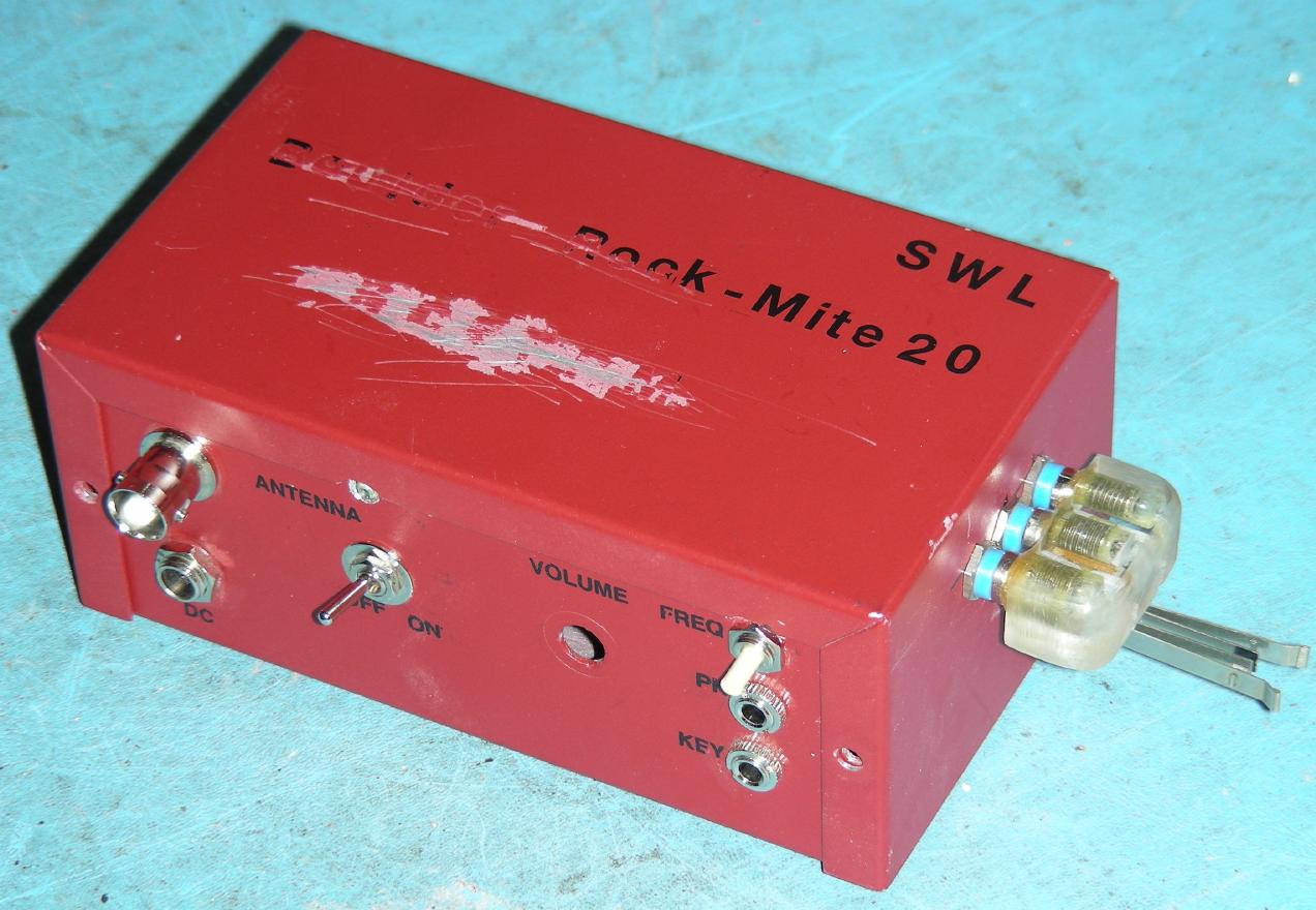
I often visit a local recycled building materials supply outlet in search of miscellaneous parts and an interesting looking pair of small electronic boxes caught my eye. The two boxes were purchased for one dollar each and taken home. After taking the boxes apart and studying the insides, I discovered that I had purchased a RockMite 20 QRP transceiver and a FreqMite frequency counter with Morse code output. Both of these devices were kits produced by Dave Benson (K1SWL) of Small Wonder Labs around 2002. The original builder of my kit had apparently scratched their callsign off of the boxes before recycling them.
I searched the Internet for information about these kits and found the schematics as well as information on numerous modifications that others had made. There were also quite a few dead links due to the age of these kits. The information I found was sufficient to get the RockMite 20 up and running with a small amount of effort. This article will focus on the RockMite 20 and the modifications I performed to improve the operation of the kit.
The RockMite 20 is an impressive design, it is a complete 20 meter Morse code transceiver with a built-in keyer, all on a circuit board that is smaller than a business card. The RockMite 20 works on one of two frequencies, 14.0593 or 14.06 Mhz. The direct conversion receiver is very sensitive and the kit puts out about 200mW of RF power. However, after playing with the RockMite for a while, I found that it was very hard to listen to with headphones due to loud T/R switching transients, a very loud keying sidetone signal and wide audio bandwidth. There was also some audible feedback happening in the circuit. Time to start some circuit hacking.
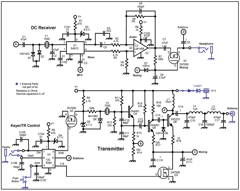
The original schematic is shown above, note that this is for the 40 meter version of the kit. There are some different values for the crystals, inductors, varactor and some of the capacitors in the 20 meter version of the kit.
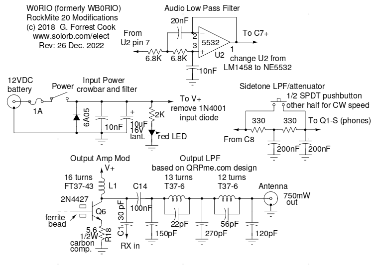
I noticed that the original op-amp chip was a dual unit (LM1458) with one half unused. I took the unused op-amp and built a 2nd order audio low-pass filter with two resistors and two capacitors. This filter was inserted between the original audio amplifier and the mute/headphone output circuit. A board trace had to be cut and the extra parts were mounted on the bottom of the board. The low pass filter removed lots of unwanted high frequency interference and noise from the audio, allowing the operator to better hear the desired lower frequency CW tones. The LM1458 was in an IC socket, so I decided to swap in an NE5532 audio-grade op-amp. The NE5532 swap is optional, but it produces a slightly less distorted audio signal.
The keyer's sidetone signal was much louder than the received signals and had an unpleasant sounding square wave tone. A simple two stage low-pass filter was built with two resistors and two capacitors, this made the sidetone much quieter and more pleasant to listen to. Unfortunately, due to the switching of the Q1 muting transistor, the sidetone modification caused the keyer speed-change tones to attenuate much more than the sidetone signal. This problem was solved by changing the speed pushbutton to a DPDT pushbutton, and wiring the second half of the pushbutton across the resistors in the sidetone low-pass filter. The operator should keep the pushbutton pressed while changing the CW speed.
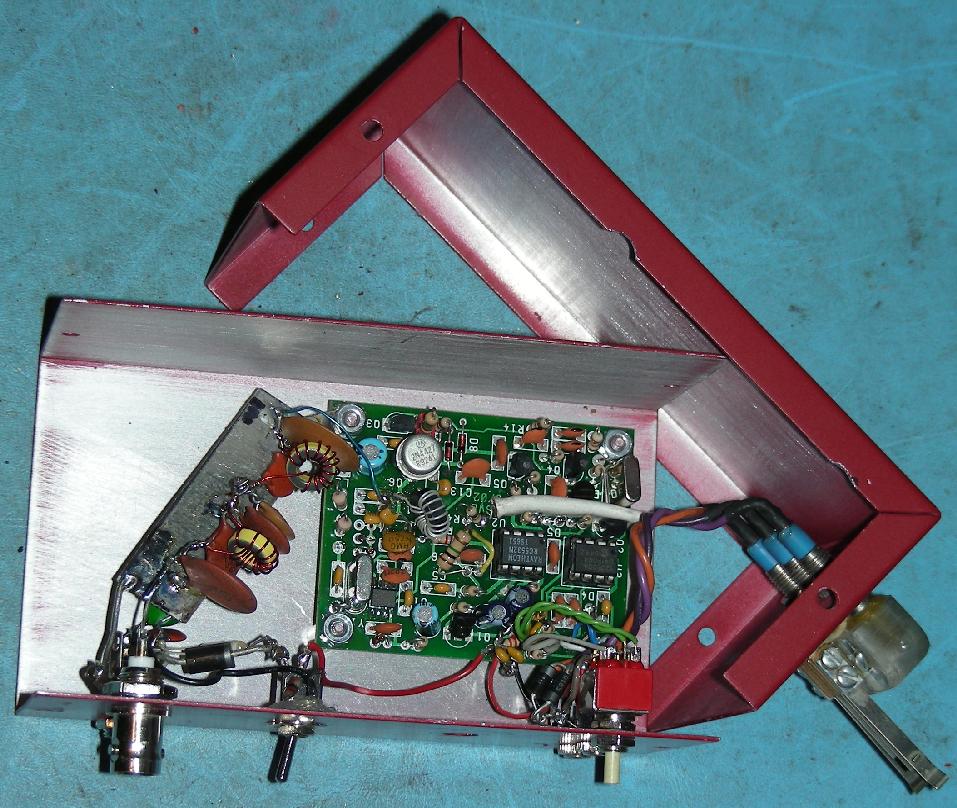
The RockMite exhibited a resonance in the audio signal that sounded like some kind of feedback was happening. By placing my finger on various parts of the circuit while it was operating, I was able to make the feedback stronger and locate some of the parts that were cauing the problem. Two resistors, R12 and R15 were connected to the oscillator circuit. The resistors were both mounted vertically and the RF "hot" side was on the longer leads. By unsoldering and reversing the resistors, the oscillator RF was made to radiate less. A piece of 1/4" metal braid was encased in heat-shrink tubing to make a metal shield. A small wire was soldered to one side of the shield and grounded near the center of the board. The shield was then wedged between U2/U3 and crystal Y2, this can be seen as the white line between the two 8 pin DIPs and the oscillator circuit in the above photo. This modification completely eliminated the feedback.
The original RockMite circuit used a tiny 2N2222A transistor for the final RF Amplifier, this produced around 200mW. 200mW is sufficient for close-in contacts or distant contacts when band conditions are good, but more power is always useful. There are numerous power output modifications available on the web, my modification was loosely based on some of these ideas, but were altered to fit the parts that I had on hand.
I removed the original Q6 output transistor, choke L1 and emitter resistor R18. I cut some machined IC socket pins from a socket and soldered them into the Q6 and R18 holes for experimentation purposes. Q6 was changed to a 2N4427 and a ferrite bead was placed on the Q6 base lead to prevent unwanted VHF oscillations. R18 was changed to a 5.6 ohm part, be sure to use a carbon composition resistor here, a spiral-plated resistor will have too much self-inductance to work properly. Choke coil L1 was replaced with a heavier coil built with 16 turns of #30 wire-wrap wire on an FT37-43 toroid core.
The improved RF output power mod and lowpass filter were borrowed from the QRPme.com design, this company still sells the RockMite kits as of 2022. See: QRP.me Power Efficiency Modification by W5USJ. Note that the impedance matching toroid transformer shown in the QRP.me article was not used here, the transformer was tried and did not show any improvement in the output power over the L1 choke arrangement. This may be related to my use of a 2N4427 transistor versus the 2N3866 used by W5USJ.
The lowpass filter components were soldered onto a small scrap of blank PC board material that was installed between the RockMite board and the RF output jack. I changed the toroid cores to slightly larger T37-6 types because I had them on hand. The filter was connected to a signal generator, a 50 ohm load and an oscilloscope to verify that it worked as it should. With the modified output transistor, choke and output filter the RockMite now puts out a solid 750mW of RF power. When transmitting, the 2N4427 transistor runs slightly warm with no heat sink.
The original RockMite circuit had a 1N4001 diode in series with the 12VDC power supply to protect against reverse voltage. That works, but it reduces the operating voltage by about 0.7V which lowers the output power and wastes battery power. I changed the DC input circuit by adding a series fuse and a heavy-duty 6A05 crowbar diode. This provides the same protection without decreasing the supply voltage to the circuit.
Another way to achieve reverse polarity protection is to use a P-channel MOSFET transistor in the power input circuit, the Source pin goes to the + input, the Drain pin goes to the V+ line and the Gate pin goes to the - input. The transistor should have a low series resistance value in order to minimize the voltage drop. Suitable MOSFETs include the IRF9520, the IRF5305 and the IRF9Z34N, many other types will also work.
A 10uF tantalum capacitor and a 10nF ceramic capacitor were added across the DC line to reduce noise feed-through from the power supply. An optional red LED with a 2K current limiting resistor was added as a power-on indicator. The LED should be a high-brightness type for the best visibility. The 2K resistor limits the current to below 5mA, which keeps the power consumption low.
A small keyer paddle was mounted on the side of the aluminum box using three pin-jacks, this paddle was borrowed from another homebrew rig that I had already built. The paddle was wired in parallel with the external paddle jack so other paddles can still be used.
The box had an extra hole for an unused volume control modification, the hole was plugged to keep dust out. The upper part of the box had to have small notches filed in the edge to accomodate the frequency shift pushbutton and a mounting screw. The case could be made to look better by adding a new coat of paint.
The modified RockMite has been used for a number of successful over-the-air conversitions (QSOs) and from my Colorado location using a simple dipole antenna. The rig has been picked up by the reverse beacon network from Virginia to British Columbia.
In conclusion, these modifications can change the RockMite from a novelty QRP rig that is difficult to use into a much more functional radio that can provide hours of fun operation.
Back to FC's Ham Radio Circuits page.