(C) 2005, G. Forrest Cook
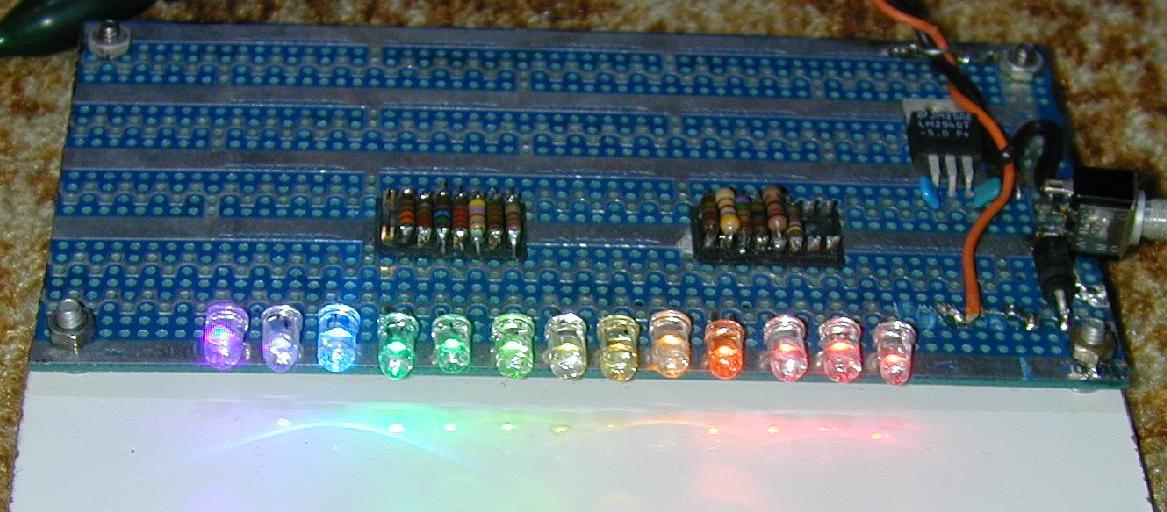
Only a few years ago, the choice of LED colors was limited to IR, red, yellow, and green (yellowish-green). The LED manufacturers have been busy extending the spectrum, and filling in the gaps. The latest generation of organic LEDs (OLEDs) has added some dazzling new colors to the spectrum. This circuit uses a set of 13 differently colored LEDs to generate a full color spectrum. The photo does not fully represent the colors generated due to camera limitations. The real-world display is very eye-catching. If you want to "trick out" your PC or favorite electronic project, this LED array will work nicely.
Operating Voltage: 6-12V DC
Operating Current: 145ma at 12V DC
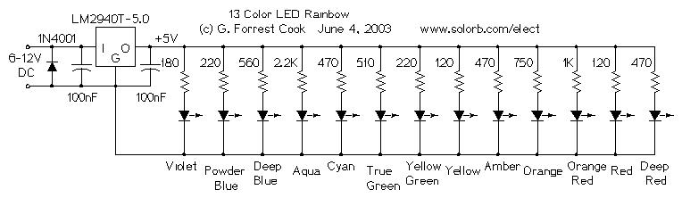
The LM2940T-5.0 low dropout voltage regulator converts the 6-12V DC input power to regulated 5 Volts. It was chosen over a standard 7805 regulator so that the circuit could maintain regulation while operating on a 6V battery. The 1N4001 diode protects the circuit from reverse polarity, if a battery or power supply capable of generating over 1 amp is used, a 1 amp fuse should be installed between the supply and the circuit.
The regulated 5 Volts is used to drive each of the LEDs through individual current limiting resistors. The resistor values were determined experimentally for equal brightness. Values are given as examples only, different sources of LEDs will require different resistor values. Resistor selection turns out to be the most difficult part of the circuit's construction. A 100 ohm resistor in series with a 1K pot could be used in place of each resistor if individual brightness adjustments are desired.
The following table lists the LED colors and wavelengths, note that Aqua and Cyan should be swapped in the schematic:
| LED Color | Wavelength | Description |
|---|---|---|
| Deep Red | 700nm | deep red |
| Red | 660nm | traditional red LED |
| Orange-Red | 635nm | "high efficiency" red |
| Orange | 623nm | also called red-orange |
| Amber | 594nm | yellow-orange |
| Yellow | 588nm | traditional yellow LED |
| Yellow-Green | 567nm | traditional green LED |
| True Green | 555mn | emerald green |
| Aqua | 525nm | greenish blue |
| Cyan | 505nm | blueish green |
| Deep Blue | 470nm | ultra blue |
| Powder Blue | 430nm | first generation of blue |
| Violet | 410nm | near UV |
The circuit was built on a prototype perforated board with printed solder pads. The circuitry is hand-wired on the back side of the circuit board. Be careful not to overheat the LEDs when soldering, use a clip-on heat sink on the LED wires. Care should be taken to avoid zapping the LEDs with static electricity, use a grounded soldering iron and a static-free workspace. The circuit board should be mounted on a piece of white hardboard to prevent shorting out the wiring on the bottom, the white paint reflects the colors nicely.
Apply power to the circuit and enjoy the colorful glow. Be sure to apply power with the correct polarity. Do not stare directly into the array at close range for extended periods, some of the LEDs are extremely bright.
The colors in this project were chosen for an evenly spaced color spectrum. The spectrum could be extended on both the IR and UV sides as well as the middle. A brief scan through the Mouser catalog indicates the availability of these IR wavelengths: 940nm 880nm, 875nm, 870nm, 850nm. UV-A LEDs at 400nm, 395nm, 380nm, 360nm and 350nm are also available. Recently developed UV-B LEDs include 290nm, 280nm, 270nm, 265nm and 255nm. The LEDmuseum has a list of available UV-A and UV-B LEDs. There are also many LED colors available with wavelengths between the 13 colors shown. The industry is slowly converging on standardized color names. One interesting and recently developed LED color is Royal Blue, which emits light at 450nM.
An open-collector LED driver circuit could be connected to the negative LED leads for computer control.
The circuit could be used in conjunction with a photo detector for characterizing optical filter curves. Typically, the photo detector output is sent to a logarithmic converter, the log-ratio of the direct light versus the filtered light characterizes the attenuation at a given wavelength. It may be possible to use an array such as this as a multi-wavelength light detector, LEDs of a given color tend to work as photo detectors that are sensitive to the same color.
Most of the LEDs were purchased from Digi-Key, Jameco, and Mouser. All of the parts were T1-3/4 size, all of the LEDs were in clear non-diffused packages. LEDs from different manufacturers may have different focus characteristics. All of the resistors are 1/4 Watt parts. The LED part numbers are not shown, the rainbow was assembled from parts that were accumulated over several years. Beware that different LED manufacturers use many names for their LED colors, the peak wavelength is the best indicator of the color.
The large electronic distributors such as Mouser, DigiKey, Jameco and Newark all carry vast selections of LEDs, the tricky part is assembling a set of LEDs with similar brightness levels and lens patterns. The selection of available LED types and colors is expanding rapidly.
I find it somewhat amazing that as far as I know, no LED manufacturer has produced a commercial packaging of colored LEDs similar to this project (as of 2009). It would be wonderful if a company would assemble 8 or 10 unique colors into a standard DIP VU meter LED block. I would love to hear about such a part if it ever becomes available.
The Regulated 24 Watt Broad Spectrum LED Lamp project takes the multi-color LED array to a higher power level but with fewer colors.
See my Fluorescent Magic Eye Tubes page for some older visually interesting electronic devices.
You can run this circuit from solar power with a CirKits solar kit.
Back to FC's LED Circuits page.