The goal of this project was to produce a self-contained reading lamp that was designed to be used by students in developing countries for reading at night. The circuit can also be used for a wide variety of lighting applications.
The reading lamp consists of a small solar panel, a standard UPS style lead acid battery, and a circuit board with the LEDs and other electronic parts. The circuit board contains a low power solar charge controller (regulator), a set of 8 white LEDs, a switch, an LED current regulator and a low voltage disconnect. The circuit will insure a long battery life by preventing over charging and excessive discharging. The reading lamp was designed to work with lead acid batteries, it will also work with a string of 10 NiCd or NiMh cells. The circuit is protected against reverse connection of the battery, making it goof-proof.
Newer VW and Audi automobiles come with small solar panels for keeping the battery charged in the sales lot. At the time this article was written, these panels were available on eBay for around $15 and were a perfect fit for this project. Other small solar panels can be used as long as they have an open-circuit voltage that's around 18V and a short-circuit current in the 100mA to 1A range. An inexpensive 12V 7AH lead acid gell-cell battery that is typically used for computer UPS and alarm applications is a good fit for this circuit. Be sure to use a new battery, used lead-acid batteries are almost never any good and should just be recycled.
Solar charging current: 150 ma - 1 Amp
Voltage drop through charge controller: 0.5V typical
Nominal battery voltage: 12 Volts
Battery rating: 3-7 amp hours
LED lamp current: 100ma regulated, 25ma per LED pair (1.2W nominal)
LED regulation range: constant light level from 11V to >15V
Low voltage disconnect: gradual current drop from 10.8V to 9.8V
Night time battery current drain with LED off: almost zero
Light duration: approximately 70 hours with a 7AH battery
Charge time: approximately 40 hours max, several hours typical
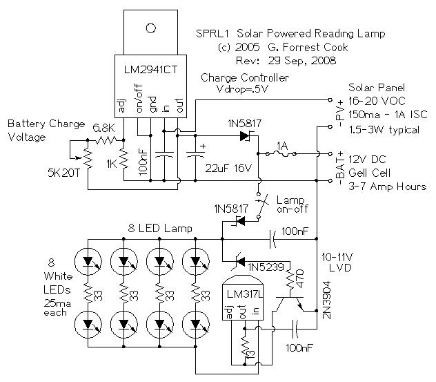
Charge Controller: The charge controller section consists of an LM2941CT low dropout voltage regulator and a 1N5817 schottky diode. The regulator determines the battery full voltage, this set-point is adjusted by the 5K 20 turn trimmer potentiometer. The 1N5817 schottky diode prevents the battery from discharging through the voltage regulator during the night. It also protects the circuitry against reverse battery connection. The fuse prevents short circuits from burning up the battery wiring.
LED Circuitry: The 8 white LEDs are connected in series with an LM317L IC that is wired as a constant current regulator. The 13 ohm resistor sets the regulated current to 100ma. This current is split evenly through the four pairs of LEDs. The 33 ohm resistors help to keep the current through the four LED pairs balanced evenly. The 2N3904 transistor, 1N5239 zener diode, and 470 ohm resistor form the Low Voltage Disconnect (LVD) circuit. Current through the LED starts to drop when the battery voltage drops below 10.8V, the circuit shuts off almost all of the current when the battery drops below 10V. The 1N5817 schottky diode blocks current flow in the event of a reverse battery connection.
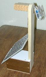
The lamp consists of a small wood battery box and a vertical board for holding the LED assembly and solar panel. A small carrying handle protrudes from the top of the vertical board. The LED assembly consists of a small printed circuit board and the various parts. It is sandwiched between a piece of hard-board and a piece of clear plexiglass to protect the circuitry from physical damage and short-circuiting. The battery used for this device is a standard 12V/7 Amp-hour gell cell UPS battery. The solar panel shown in the photo was home-made, two or three parallel-wired GM-684 12V 60ma solar panels (p/n 08SLC09 from Elecronix Express), or a VW panel can also be used.
[]Connect the board's BAT - terminal to the battery - terminal.
[]Connect the board's BAT + terminal to the battery + terminal.
[]Connect the board's PV - terminal to the solar panel - terminal.
[]Connect the board's PV + terminal to the solar panel + terminal.

[]Point the solar panel toward the sun.
[]Measure the connected solar panel's voltage with the meter.
[]Measure the battery voltage with the meter.
The solar panel must be at a higher voltage than the battery for the
circuit to charge the battery.

[]Turn the potentiometer, VR1 25 turns clockwise.
[]Monitor the battery voltage, as the battery charges, the voltage should
rise above 13V.
[]When the battery voltage has reached 13.8V or the desired full point,
turn VR1 counter-clockwise until the battery voltage stabilizes.
[]Let the battery charge for several minutes at the full setting, then
re-adjust VR1 for the final desired full voltage setting.
Daytime: Place the solar panel in a location that gets at least a few hours of direct sunlight each day. Turn the LED switch off. If the battery is extremely discharged, it may take several days in the sun to fully recharge.
Night: Use the lamp as you would use any other reading lamp. If the lamp starts to dim, the battery is almost completely empty, shut the light off. If you forget to shut off the lamp, the LVD circuit will shut the lamp off when the battery is nearly empty. If the lamp is recharged daily, the battery should rarely reach the Low Voltage Disconnect (LVD) point.
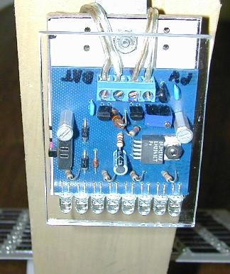
Lamp PCB with charge controller and LVD circuitry
The PCB artwork for this project is available as Eagle CAD source files.
Back to FC's LED Circuits page.