(C) 2021, G. Forrest Cook
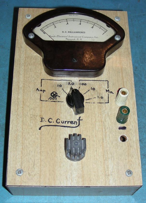
This meter came from a ham radio estate sale, it looked like an useful device so I paid a few bucks and brought it home. The original project was probably built in the 1950s or 1960s and the meter movement looks to be from the 1930s or 1940s. A multi-range DC current meter is a handy tool for any test bench. It makes a good companion for working along side a modern digital voltmeter (DVM) and is useful for working with a variety of electronic circuitry.
A few of the many uses for this meter include measuring the current consumption of low and medium power DC circuits, checking cathode, grid and screen currents in vacuum tube circuits, and testing the short-circuit current capabilites of photovoltaic panels.
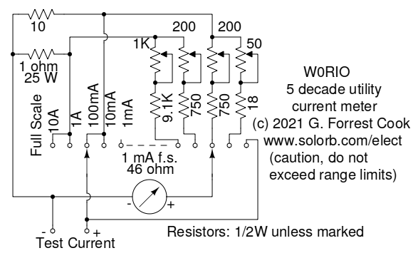
Current ranges: 0-1mA, 0-10mA, 0-100mA, 0-1A, 0-10A.
5 Amps max continuous current for the 10A range, up to 10 Amps
at 50% duty cycle.
Approximate insertion resistance: 1mA scale:46 ohms, 10mA and 100mA scales:10 ohms,
  1A and 10A scales: 1 ohm
Accuracy: approximately 2% with a high quality meter movement after calibration.
This is a straightforward current meter design that places a shunt resistor across the Test Current tie points via a range selection switch. A small amount of the test current is diverted through the meter, fixed resistor and calibration trimmer resistor on the highest of the four ranges. On the 1mA range, the meter is placed directly across the Test Current tie points.
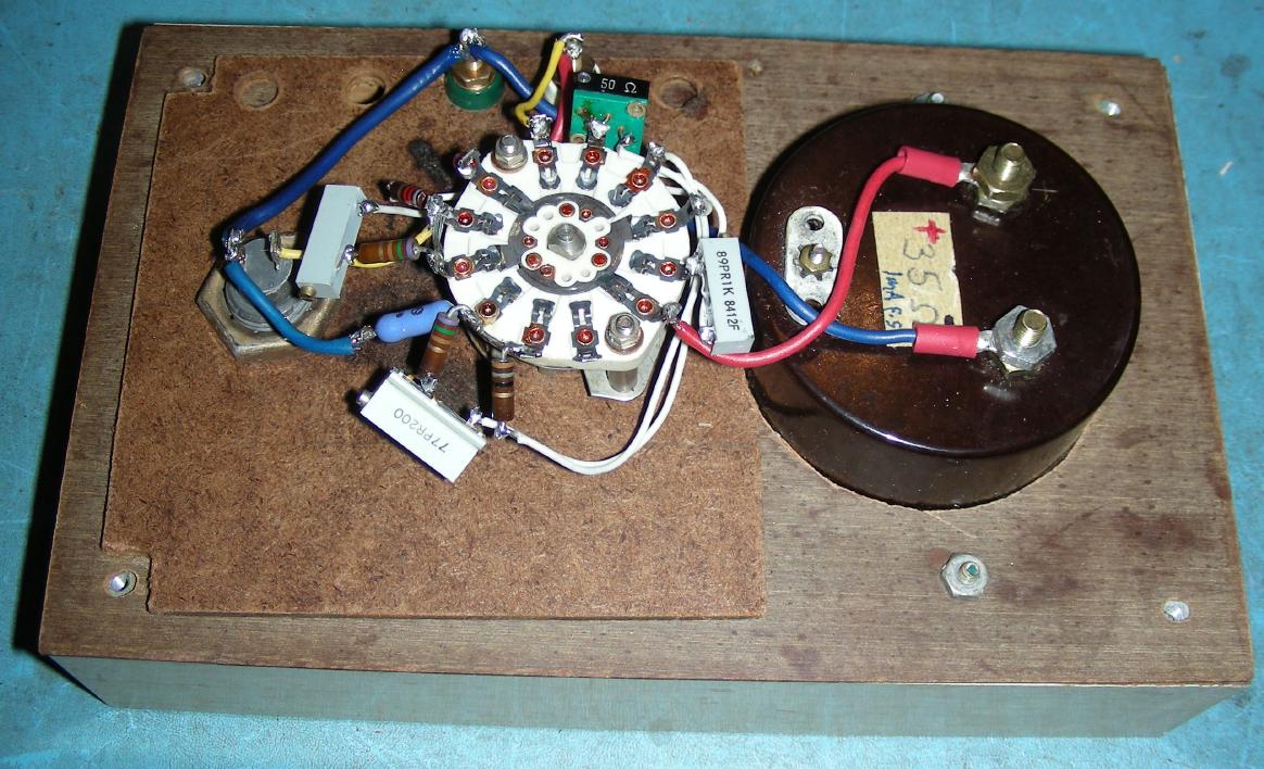
After taking the meter home and opening it up, I discovered that the insides were in poor condition and only 2 of the ranges were somewhat functional. Some kind of thick, gloppy solder flux had been used on the components and the remaining shunt resistors were home-made with magnet wire on old coil forms. Calibration had been done by removing turns of wire from the coils. The original circuitry was completely removed and the inside of the box was cleaned with alcohol and a wire brush to remove the remaining flux residue.
An additional hole was drilled in the front of the box to hold the 1 ohm, 25W resistor. The input terminals were replaced with a pair of universal banana jacks, a new hole was drilled in the front of the box to allow for the standard 3/4" spacing on the banana jacks.
Heavy 12 gauge stranded wire was used between the banana jacks, 1 ohm resistor and range selector switch. The rest of the wiring was done with lighter gauge stranded wire. The remaining resistors and trimpots were attached to the various switch tie points. This is somewhat light-weight construction, it would be a good idea to secure the trimpots to the back of the front panel with hot glue.
The meter zero setting should be set to zero before aligning the five current scales, it is usually a small screw in the middle of the meter's front panel.
The meter should be placed in series with another meter that is known to be reasonably calibrated, I used a Fluke 77 DVM. A current-limited power supply should be placed across the two meters in series, be sure to start the power supply with the lowest voltage setting.
To produce a current-limited power supply, take a variable voltage DC power supply and place a resistance in series with the supply. Using Ohm's Law in the I=E/R form, a 10V supply will produce 10A with a 1 ohm resistor, 1A with a 10 ohm resistor, 100mA with a 100 ohm resistor, 10mA with a 1K resistor and 1mA with a 10K resistor.
Adjust the power supply voltage above or below 10V for each range so that the calibration DVM measures the full-scale reading for each range. Adjust the trimmer potentiometer for each range for a full-scale reading on the meter.
There is no calibration potentiometer for the 1mA scale, the meter should be self-calibrated on that range. If you don't have a variable DC supply that's capable of producing 10A, adjust the supply for its highest current and adjust the 10A scale's trimmer to agree with the reading on the series VOM.
The first and most important thing to know is that the meter movement can be easily destroyed if too much current is run through it. This is especially true for the 100mA, 10mA and 1mA scales. Always start measuring current in the 10A range, then move the range switch to the more sensitive settings to get a more accurate reading.
If you expect that the current you are measuring will go up in value, be sure to use a scale where the meter will always read below full-scale. Most meters can handle at least 50% above their full-scale reading without sustaining damage. Also note that it is not a good idea to change the range switch when more than about an amp of current is flowing through the circuit, the switch contacts may be damaged by the resulting sparks.
After observing the above caveats, place the meter in series with the circuit that you are working with, apply power and read the current. It may be necessary to split an existing circuit open in order to install the current meter in series. If you are working with high voltages, such as when measuring some vacuum tube circuit currents, take precautions to not expose yourself to high voltages. Use well-insulated test leads and avoid any contact with live wiring.
Back to FC's Meter Circuits page.