(C) 2014, G. Forrest Cook
|
|
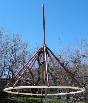
This 1/4 wave vertical ground-plane antenna project is a useful alternative to the J-Pole antennas that are often used with micro power and low power FM (LPFM) broadcast transmitters. The high efficiency of this antenna makes it especially useful for micro-power transmitters where every milliwatt counts. The radiation pattern of the ground-plane antenna is similar to that of a correctly tuned J-pole, but this antenna has several advantages.
The ground-plane antenna with sloping radials (40 degrees from vertical) has a characteristic impedance that is close to a perfect match for 50 ohm coaxial cable. The tricky step of aligning the coax clamps on a J-pole for a good match is eliminated. Compared to a J-pole, the ground-plane antenna is much less sensitive to de-tuning caused by buildings, trees and nearby metal objects since it has its own ground system (counterpoise).
For comparison, a ground-plane vertical antenna with horizontal radials would have an impedance of around 35 ohms, a matching network would be required to work with a 50 ohm coax feedline. Matching networks can absorb power and may be difficult to adjust.
This antenna is also useful as a high-performance omni-directional FM broadcast receiving antenna. For receive-only use, inexpensive 75 ohm cable TV coax or 50 ohm RG-58 coax can be used for the feedline. When the antenna is used for transmitting, low-loss RG-213, RG-8 or even hardline coax should be used. The feedline should be as short as possible to reduce cable losses.
The two galvanized floor flanges should be temporarily screwed together with the 1/4-20 hardware in order to drill out the additional radial mounting holes. Mark four points between the four existing mounting holes and use a metal punch to start the new holes. Use a 1/8" drill and cutting oil to make four pilot holes. Use a 1/4" drill and more cutting oil to enlarge the four holes to their final size. A drill press is highly recommended for this operation, be sure to clamp the material securely before drilling.
Cut eight pieces of 1/2" copper tubing to 31" long. Compress one inch of each piece of 1/2" copper tubing flat in a bench vise. Mark and punch the center of the flat part of the copper tubing, 1/2" from the end and drill a 1/4" hole in these locations. This will be used for mounting to the flanges. Mark and punch the opposite end of the 1/2" copper tubing, 1/2" from the end and at the same angle as the hole through the flat end. Drill a 5/32" hole through the round end of each tube, this will be used for mounting to the PEX tubing.
Use a propane torch to heat the flat end of each 1/2" radial tube. When the tube is hot, quickly place it in a vise and bend the flat end to approximately a 45 degree angle. Re-heat the bent section with the torch to anneal the metal. Use tin snips to remove two small triangles from the flat end of the 1/2" pipes, this will prevent the pipe ends from overlapping. When you have constructed all eight radials, use the 1/4-20 screws and aircraft nuts to mount them to the bottom of the pair of flanges. Do not fully tighten the screws on the radials yet.
Cut the PEX tubing to 122" and insert the compression connector to make a circle. The PEX tubing that was used had a natural curve that was very close to a 122" circle. Using an indelible marker, draw lines every 15-1/4" around the PEX tubing to locate the radial endpoints. The first hole was started in the middle of the compression connector, 1" from the end of the tubing. Place the radial assembly over the PEX loop and use the 5/32" hole in each radial as a guide to drill a 5/32" hole through the PEX tubing at each marked point. Be sure to drill through the longest width of the PEX tubing. Install a 6-32 screw and matching aircraft nut where the radial end joins the PEX tubing, then move to the next radial and drill the next hole. When all of the radials have been mounted, snug up all of the 6-32 screws and nuts, then center the radials and snug up all of the 1/4-20 screws at the top.
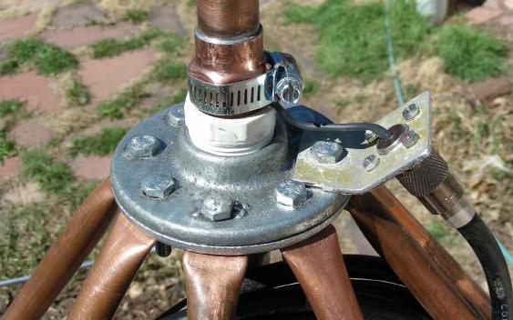
Build the PL-259 adapter plate. I used a hack saw to cut the aluminum plate, then drilled and filed the connector holes and drilled the 1/4" mounting hole. After the adapter plate has been fully drilled, place it in the vise and use a hammer to bend it to a 45 degree angle. Install the PL-259 connector to the plate with the 4-40 mounting hardware and mount the adapter plate onto the flange through using one of the 1/4-20 radial mounting bolts. Solder the 12 gauge wire into the PL-259 connector center pin and put the heat shrink tubing over the wire, leaving about 1/2" of bare wire at the end.
Insert the 1" to 3/4" PVC pipe adapter (insulator) into the top flange piece, the adapter should be screwed in tightly. Solder the 3/4" threaded copper pipe adapter to the end of the copper pipe and screw the pipe into the PVC insulator. Hand-tighten this piece, it will need to be removed several times until the antenna has been tuned. Bend the coax center wire so that it lines up with the lowest part of the 3/4" copper pipe adapter piece and clamp the wire to the adapter with the compression clamp.
Screw the galvanized mounting pipe into the bottom of the flange assembly and temporarily install the antenna in a location where you can easily remove the top section for tuning.
If you expect to operate this antenna in a windy environment such as on a tall tower, it is recommended that you install a wooden cross brace across the mounting pole and the base of the PEX tubing loop. This will prevent movement of the radials that will eventually lead to metal fatigue and cracking where the radial tubes bend.
If built exactly as specified, the antenna should start out very close to resonance in the lower part of the FM broadcast band. An MFJ-259 antenna analyzer was used to plot the center frequency and bandwidth of the antenna. If you don't have access to an antenna analyzer, observe the SWR while transmitting at several different frequencies, the resonant point will have the lowest SWR. Note that the small copper link from the center of the coax connector to the base of the vertical element will affect the resonant frequency, it should be as short and straight as possible.
The vertical element was originally cut a few inches long and then trimmed 1/2" at a time until the antenna was a perfect match at the desired frequency. The 3/4" copper end cap was soldered to the top of the pipe after cutting. The end cap can be heated with a torch and slid up and down for fine-tuning. Longer lengths will resonate at lower frequencies. In the original prototype, the full length of the vertical section including the cap and pipe adapter was 27-1/4" (90.0 Mhz), your mileage may vary depending on the construction details.
It is a good idea to weatherproof the antenna to prevent corrosion of the metal. A 6" PVC pipe cap with a 13/16" hole drilled in the center can be fit over the vertical pipe and will keep the coax connection and radial mounting screws dry. The weather cap also prevent the sun's ultraviolet radiation from breaking down the plastic components. The PEX loop could be painted gray or black to improve its UV resistance or black tubing could be substituted. Silicone caulk should be applied to the top of the PL-259 connector to prevent corrosion and water intrusion into the connectors. Be sure to let the silicone cure in a warm place for a few days before applying power. Un-cured silicone is electrically conductive. Black electrical tape or rubber coax tape should be wrapped around the coax connection to prevent water intrusion into the coax.
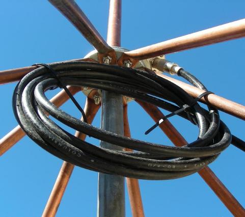
The coax feedline should have a two turn loop with a radius of around 5" where it connects to the antenna near the bottom of the radials. Note that the original build shown in the photos had too many turns. The coax coil acts as an RF choke to prevent the feedline from becoming part of the antenna. See this G3TXQ article for more information on choke coil designs. The coax coil should be tied together and secured to the mounting pole with the black Panduit ties. The remaining coax should be routed to your transmitter, use the shortest length that is practical to lower the coax line power losses.
One shortcoming of this antenna is its somewhat high radiation angle, which is also similar to that provided by a J-pole. This can be an advantage if the broadcast station is located in a valley, but if you are broadcasting from a flat location or a hilltop, a lot of power will go out at a higher angle than is desirable.
One way to lower the radiation angle is to change the vertical radiator from a 1/4 wave element to a 5/8 wave element. The 5/8 wave vertical will focus the majority of its radiated power out at a much lower angle than the 1/4 wave vertical does. The disadvantage of the 5/8 wave antenna is that it requires a tapped matching coil at the base of the vertical element that transforms the impedance to 50 ohms. The matching coil will require some tricky adjustments, an antenna analyzer is highly recommended for this process. Your author has not yet experimented with the 5/8 wave version of this antenna.
For those wishing to experiment, this design allows different vertical elements to easily be screwed in and tested. The ground radials will work as-is with either type of vertical element in the lower frequency part of the FM broadcast band. If you want to use the antenna on a higher frequency part of the FM band, it may be necessary to shorten the radials a bit. Typically radial elements are 5 to 10% longer than the vertical element.
In this antenna, the steel mounting pole is electrically connected to the radial hub, and becomes part of the antenna's counterpoise system. If the mounting pole is attached to a metal tower, the tower also becomes part of the antenna's counterpoise. This may cause a distortion in the antenna's radiation pattern. To achieve a radiation pattern that is closer to that of a perfect ground plane antenna, the mounting pole should be shortened so that is less than or equal to the length of the radials. The shortened mounting pole should be mounted to a heavy piece of PVC pipe or piece of wood that is painted with polyurethane. It may be beneficial to move the coax choke loop down to a height that lines up with the bottom of the radials. See this article for a detailed explanation of this issue.
This antenna will work with just four radial elements but it will not be as physically stable as the 8 radial version. Eight radials will also produce a more even radiation pattern. If you want to start with just four radials, it is a good idea to drill the extra holes in the flange plates so that more radials can be easily added at a later time. This article by KK4OBI compares the effects of adding radial elements to ground plane vertical antennas, one of his conclusions is that six radials is the optimum number. A six radial antenna would require drilling holes in the flange plates at 60 degree intervals.
Back to FC's Micro Power FM Broadcasting page.