(C) 2010, G. Forrest Cook
There are many miniature FM transmitter (bug) circuits online, this one is unique in that it runs completely on solar power. No battery is required and the circuit will work for many years. As long as the sun is shining on the PV panel, the bug will transmit. The transmitter is useful as a "remote ear", and can be used for a variety of purposes such as listening to birds or surveillance. The mic preamp and oscillator circuits were borrowed from a common circuit that can be found on the Internet. An RF amp was added to extend the bug's range, it also improves the frequency stability by isolating the oscillator stage from the antenna. The solar power supply provides regulated voltage as long as the PV panel is exposed to sunlight.
This transmitter can also be powered by a regular 9V battery, just replace the PV panel and 78L09 regulator circuitry with a battery and a power switch. A standard 9V battery will not last long, a better choice would be to use a set of 8 AA size NiMH rechargeable cells in series or possibly a pair of 3.7V LiFePo cells in series. Note that there will be more frequency drift when running the bug from batteries since the supply voltage will change as the batteries discharge. Three LiFePo batteries feeding the 78L09 regulator circuit would improve the drift. Be sure to include a series fuse (1/2A) when running the bug on battery power.
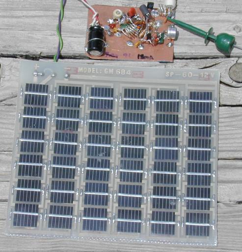
The solar power supply consists of a small 18V PV panel which charges a 1000uF electrolytic capacitor. The capacitor keeps the circuit running during brief interruptions of light, such as when a bird flies over the PV panel. The PV panel's 18V open circuit voltage is regulated down to 9V with the 78L09 regulator IC which provides a steady 9V supply for the rest of the circuitry. With the PV panel shown above, the circuit will only work when direct sunlight is shining on the panel. A larger panel that can provide 22mA at 12V during cloudy conditions would extend the circuit's operating conditions.
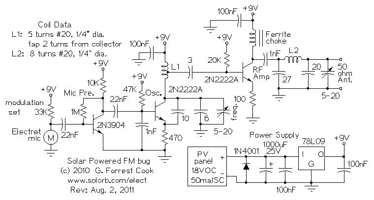
The Electret microphone is biased with a 33K resistor, the resistor value can be changed to vary the amount of modulation and optimize the performance of specific microphones. The microphone signal is amplified by a 2N3904 class A audio amplifier. This signal is sent to the 2N2222A oscillator stage where it changes the oscillator's frequency (FM). The oscillator's center frequency is set by L1, the 6pF capacitor and the 5-20pF variable capacitor. With L1 wound as specified on the schematic, the circuit will operate near the low end (88Mhz) of the FM broadcast band.
The output of the oscillator circuit is taken from a tap on the oscillator coil L1 and is fed to the 2N2222A RF amplifier transistor. The output of the RF amp is run through a low-pass PI filter to remove unwanted RF harmonics before the signal is sent to the antenna. The low-pass filter also helps match the impedance of the RF amp to the antenna.
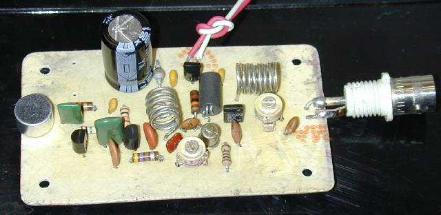
The prototype circuit shown in the top photo was built using the "dead bug" construction method, it was laid out as the circuit was designed. A second-generation version of the circuit was built using a home-made printed circuit board, this is shown in the second photo. The frequency stability of the transmitter was greatly improved when it was built with the circuit board. The PCB fits nicely in an Altoids mint tin box. Artwork for the PCB is available at the end of this page.
It important to mount the oscillator components solidly so that they don't move around and cause unwanted frequency shift. The component leads for all of the RF wiring should be kept short. The coils were tight-wound on a #2 Philips screwdriver shaft then stretched out. To improve the circuit's frequency stability, wind the oscillator coil on a 1/4" form, then heat the coil in an oven at to anneal the metal. A layer of polystyrene "Q dope" or hot glue can be used to cover the coil to further improve the stability.
Another trick that will improve the transmitter's frequency stability is to build it into a metal box and surround the box with an insulating material such as styrofoam or bubble-wrap. If the transmitter box is mounted in the shade, it will be less likely to change frequency due to solar heating and cloud shading.
This circuit will work with a variety of antennas. An adequate short-range antenna can be as simple as a 1' to 2' wire connected directly to the circuit. A resonant antenna such as a tuned dipole or a vertical antenna will greatly extend the range of the transmitter.
A resonant half-wave diple antenna for 90Mhz can be made with two 2.6 foot pieces of wire fed in the middle with a short length of 50 ohm coax. The lengths of the two halves of the dipole can be calculated using the classic dipole formula: quarter wave length (feet) = 234 / frequency (Mhz). The antenna should be kept away from nearby objects including the PV panel and its wiring.
Another antenna setup that would work would be to use a short quarter wave vertical wire for the top of the antenna and the PV panel and its wiring cut to a quarter wave hanging down to form the bottom part of the antenna. The circuit board should be mounted in the middle with the entire assembly suspended from the top with plastic rope.
The circuit can be aligned on the work bench by putting 12V to 18V DC across the PV panel to power the regulator. Tune your receiver to a blank spot on the lower end of the FM band and adjust the frequency calibration trimmer until you hear the microphone signal. Turn the trimmer very slowly, alignment takes a light touch. Don't turn the receiver volume up too much or you will get audio feedback. A frequency counter may be useful for setting the output frequency. It may be necessary to retune the frequency a bit after the circuit has warmed up in the sun.
The output capacitor should be tuned for the maximum transmitted signal, this setting varies with different antennas. The best way to do this is to connect the antenna to the transmitter and monitor the signal with an oscilloscope (100 Mhz bandwidth) connected to a nearby antenna. Adjust the control for the highest signal. If you have a receiver with a signal strength indicator, that can also be used for monitoring the transmitter's output level. Adjustment of the output capacitor will pull the oscillator frequency a bit, it will be necessary to alternate between oscillator and output adjustments to fully align the circuit.
Place the PV panel in the sun and tune your receiver to the bug's signal, listen to the world outdoors. An analog receiver is best for picking up the signal since, unlike a digital receiver, it can be fine tuned to track the signal. I use a 1970s vintage Pioneer receiver to good effect. Once the bug's temperature has stabilized, its frequency should not drift very much. It may be useful to tune the bug slightly below 88 Mhz if your receiver can tune there, doing so will reduce interference from broadcast stations.
For the best signal strength and range, the receiver's antenna should be mounted in the same vertical or horizontal orientation as the bug's antenna and the two antennas should be parallel to one another.
The microphone enclosure and placement can be tuned to optimize sound reception in a particular direction. A good directional microphone can be made by putting the mic element into one end of a short piece of PVC pipe. Inserting a thin tube of porous foam into the pipe can lower the resonant nature of the cylinder.
Back to FC's Micro Power FM Broadcasting page