(C) 2020 G. Forrest Cook

This device is intended to be used in conjunction with an old-school stereo receiver/amplifier. It monitors the receiver's audio input and if no signal is heard for a selectable number of minutes, power to the receiver is shut off. This reduces power usage and prevents hours of unnecessary heating that can cause wear and tear on the stereo's circuitry. The device can be thought of as a negawatt generator.
The Auto Shut-Off circuit can be used with a stand-alone stereo. It is especially handy for controlling a remote amplifier in a distributed sound system.
This device uses 120VAC high voltage. The project should only be taken on by someone who has experience working with high voltage circuitry.
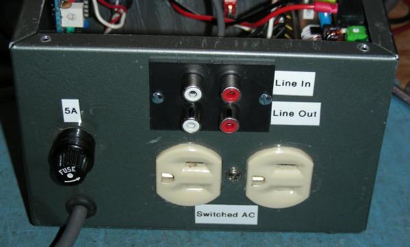
Power Input - 120VAC Line Input
Power Output - 120VAC Line Output, up to 10 Amps
Audio In/Out - line-level stereo inputs and outputs
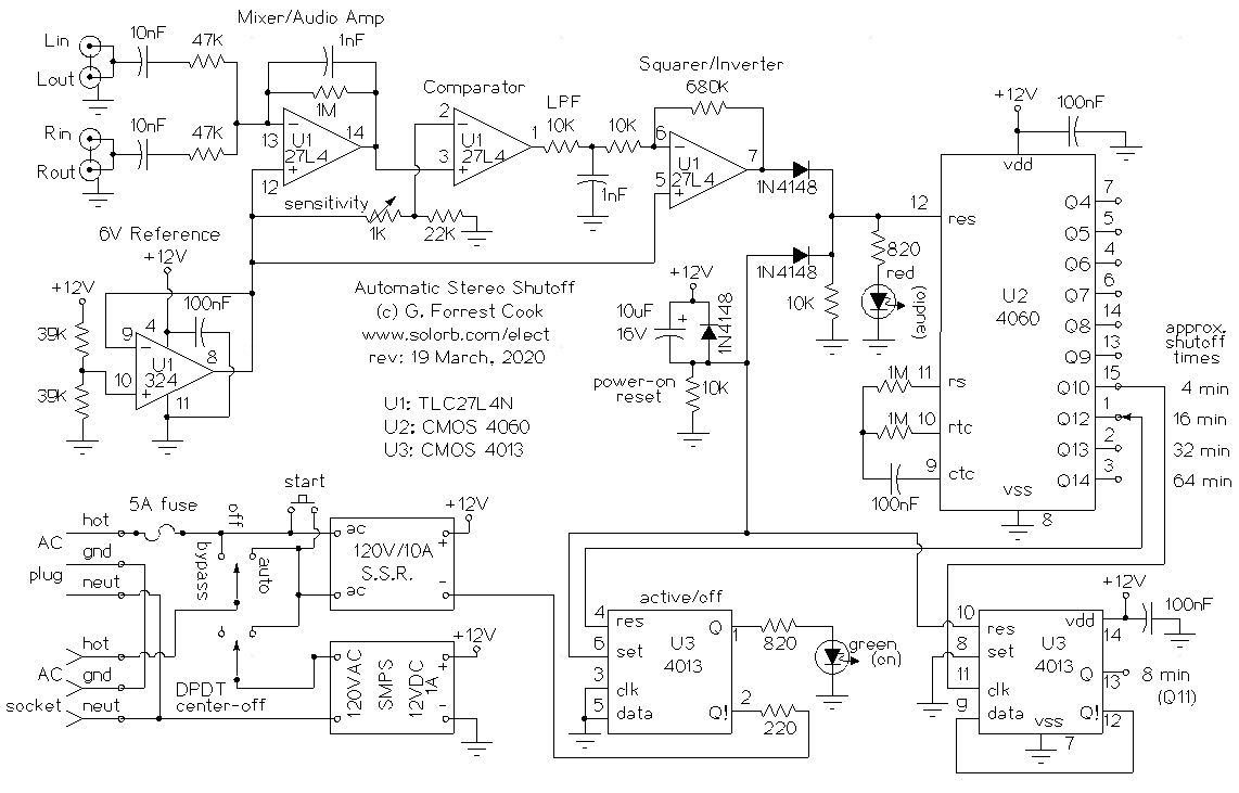
The Auto Shut-Off is powered by the 120VAC line input. When the start button is pressed, the 12VDC switching power supply is turned on, powering up the the rest of the circuit. When power is first applied, the 10uF/10K power-on reset circuit produces a brief logic high signal that clears the 4060 counter through one input of a 2 diode OR gate. The reset signal sets one of the 4013 flip-flops, which turns on the green Power LED and activates the Solid State Relay. The reset clears the other 4013 flip-flop. The diode across the power-on reset capacitor discharges the capacitor on power-down so that the reset circuit re-activates if power is cycled more than once.
One section of the TLC27L4 quad op-amp is used to produce a buffered 6 Volt artificial ground reference. This signal is used by the other three op-amp sections. Note that the quad op-amp must be a CMOS rail-to-rail type because one section of it is used to drive a CMOS logic circuit.
Line-level audio from the left and right audio inputs is sent to an op-amp mixer/amplifier circuit. The amplifier boosts each channel by a factor of 20 and the 1nF feedback capacitor reduces some of the high frequency signals. The 47K mixer input resistors were chosen to provide a high impedance to the monitored audio lines to prevent loading.
The amplified audio is routed to an op-amp which is wired as a comparator circuit. The 1K sensitivity potentiometer sets the voltage on the comparator's minus input to slightly below the 6V reference level. When the negative swing of the audio signal goes below the comparator setpoint, the output of the comparator pulses low.
The output of the comparator drives a simple low-pass filter consisting of a 10K resistor and a 1nF capacitor to ground, this removes some of the narrow switching pulses and also provides a load for the comparator to prevent RF oscillations during switching. The last op-amp secton inverts the switching pulses and also amplifies them by a factor of 68, producing a relatively clean digital signal on the output (pin 7). The output signal only pulses when audio is playing.
The output of the squarer/inverter stage is routed through the diode OR gate where it repeatedly resets the 4060 counter as long as sound is playing. The reset signal also drives the red Audio LED to give an indication of sound.
The CMOS 4060 counter has a free-running clock who's frequency is set by the resistors and capacitor on the rtc, rs and ctc lines. As long as music is playing, the 4060 counter keeps being reset. If no music is detected for the desired amount of time, the 4060 counter eventually counts up to the point where the selected output line goes high.
The 4060 counter does not provide a pin for the Q11 output, the original chip designers must have had an interesting reason for making that design. The spare 4103 flip-flop is used to divide the 4060 Q output by 2 to provide an equivalent Q11 output.
Any one of the timer output lines can be selected to provide various shutoff times. These can be selected with a switch, or just hardwired to one setting. When the selected output line from the 4060 rises, it activates the reset line on the active/off 4013 flip-flop. This removes power from the Solid State Relay input signal which causes the stereo to shut off. Power is also removed from the switching power supply. The circuit and the stereo stay off until the start switch is manually pressed.
If the Auto/Off/Bypass switch is placed in bypass mode, the AC socket is connected to the AC line and the rest of the circuit is disabled.
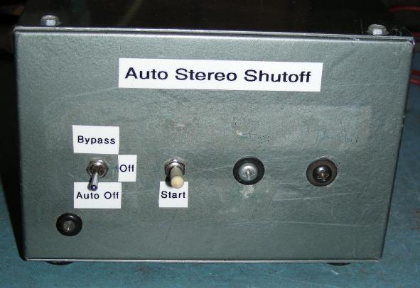
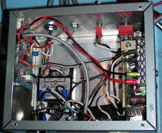
The project was built into a 7"x5"x5" aluminum utility box. Holes were drilled for the various panel-mounted components and internal modules. The power and audio LEDs can be two separate parts or a single common-cathode Red/Green LED. The op-amp and logic circuitry was built onto a small piece of prototyping circuit board using hand-wired point-to-point connections, it was mounted on the side of the box using 4-40 threaded standoffs. Circuit connections were made using tinned copper wire covered in teflon insulation.
All AC wiring should be done with wire that is sufficiently heavy for the intended load, number 16 stranded wire is recommended. The audio line should be routed from the RCA jacks to the circuit board using a small length of shielded wire. This line should be kept away from the AC wiring to prevent hum from getting into the audio signal.
Connect the Auto Shut-Off device in series with the audio line that goes into the stereo. The Auto Shut-off can also be fed by a stereo's tape monitor output line. Plug the Auto Shut-Off into the 120VAC line and plug the stereo into the Auto Shut-Off outlet.
Turn the power switch to the Auto setting, turn on the stereo's power switch and press the start pushbutton, the stereo should turn on at this point.
When setting up the Auto Shut-Off for the first time, adjust the sensitivity control to the point where the red LED does not blink when the audio line is quiet. This is typically around the half-way point for the control.
As long as audio is playing, the stereo will remain on. When the audio stops playing for longer than the selected shutoff time, the circuit will power down the stereo.
Back to FC's Music Circuits page.