(C) 2009-2022 G. Forrest Cook
There are zillions of guitar distortion circuits on the Internet, many with funny names. The FuzzniKator is somewhat unique among the lot. The circuit was inspired by the great distortion sound that tube amps give a guitar during the seconds after the power has been shut off and the signal is fading out. The effect is also similar to a cranked tube amp driving a resistive speaker attenuator. The FuzzniKator also doubles as a vacuum-tube guitar preamp, it makes a nice tube-input stage for driving multiple amps and/or effect pedals.
The circuit uses a special voltage-starved push-pull tube output stage driving an output transformer which then drives a resistive load. The push-pull output tubes are run from an adjustable (and lower than normal) B+ voltage in order to "starve" the tubes and produce distortion. The push-pull configuration and transformer output produce a more harmonically pleasant distortion compared to most diode-clipped distortion effects.
The starvation voltage and drive signal are adjustable for a wide variety of sounds. The FuzzniKator also has a clean tube preamp channel that is similar to a classic Fender amp's tube front-end circuit. The clean channel works nicely as a tube preamp stage and the distortion channel makes any amp, solid state or tube, sound warm and fuzzy. This version of the circuit adds a mixer stage to the distortion channel which allows the distorted and clean signals to be mixed together for a wider variety of sounds.
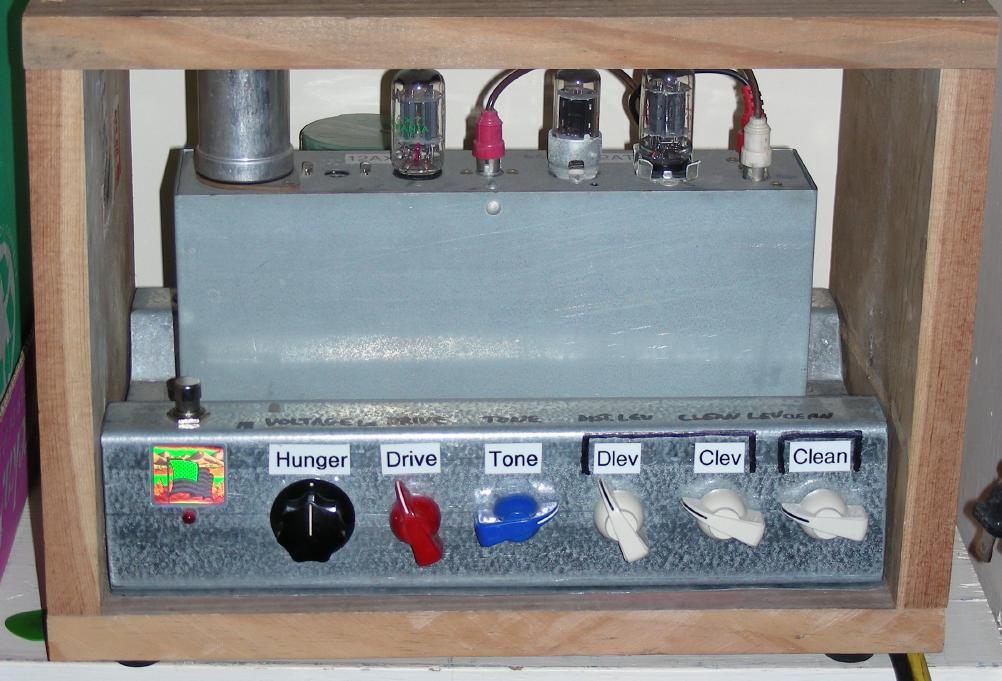
A Hammond AO-42 organ amplifier unit was used as the platform for this circuit. This is optional, but it makes a good chassis for the device and saves a lot of trouble drilling holes for the tubes and terminal strips. A Hammond AO-41 percussion unit is also a good choice for the chassis. These boxes can be found on eBay for reasonable prices.
The FuzzniKator's companion project is the Liquidator Tube Phaser/Chorus Effect, which uses a Hammond AO-47 box. The Hammond AO-42 and AO-47 boxes are often sold together on eBay auctions, prices are usually low since the boxes have no power transformer.
This circuit uses high voltages including 120 VAC and 250 VDC. The project should only be taken on by someone who has experience working with high voltage circuitry. The power should always be removed when working on the device. The circuitry is designed to discharge the capacitors when power is removed, but it's always a good idea to short out the electrolytic capacitors before working on the circuitry.
AC Power Input - grounded 120VAC
Guitar Input - High Impedance
Amp Output - Medium Impedance
On/Off (on the back)
Clean/Distort foot switch
Hunger (starvation voltage)
Distortion Drive
Distortion Tone
Distortion Mix Level for distortion channel
Clean Mix Level for distortion channel
Clean Signal Level for clean channel
Master Output Level
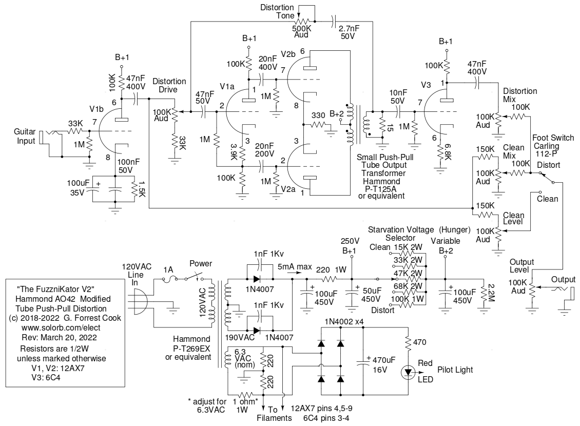
The guitar signal drives V1b, a cathode-biased class A triode amplifier. The output of V1b is attenuated through the Clean Level control and sent to the SPDT foot switch as the Clean signal. The output of V1b also goes to the Distortion Drive control and on to V1a, which is wired as a cathodyne phase inverter.
The two out-of-phase drive signals from V1b are fed to the grids of triodes V2a and V2b. The plate circuits of V2a and V2b drive the output transformer in push-pull mode. The push-pull stage runs with low B+ values and high grid drive, this produces the Fuzznikator's distortion. The output transformer drives a 15 ohm load resistor which is important for producing good tone.
The output transformer's signal is routed back to the V1a input as a negative feedback high-cut Tone control. The distorted output signal also drives V3, a 6C4 triode wired as a class A amplifier. The 6C4 buffers the output and also inverts its phase so that the distortion and clean signals are sent to the mixer with the same polarity. Half of a more-common 12AU7 tube could be substituted for the 6C4.
The distortion and clean signals are mixed together using two 100K potentiometers and 100K resistors. The clean signal level is adjusted with a third 100K potentiometer. The foot switch selects between the distortion mixer signal and the clean signal. The Output Level control sets the overall level for both the Clean and Distort modes.
It is possible to substitude different tubes in the V2 distortion amplifier circuit. The 12A*7 tube family share the same pinouts but have different amplification factors. A low-gain 12AU7 produces a smoother sounding distortion and a high-gain 12AX7 produces more of a crunchy sounding distortion. The medium-gain 12AT7 produces a distortion sound that is between the other two tubes.
The power transformer has a standard fused and switched line input. The 6.3 VAC output powers the filament circuits for the two tubes. It also drives a bridge rectifier and filter circuit to provide DC for the optional LED pilot light. The transformer's high voltage output is full-wave rectified and R-C filtered to produce B+1 (around 250V). The B+1 voltage is used to drive the clean preamp and phase inverter stages. The B+2 voltage is adjustable and it drives the push-pull output stage. A multi-pole Starvation switch selects different dropping resistors to produce a variable B+2 voltage. A 2W 100K variable resistor in series with a 15K 2W pad resistor could be used in place of the switch to give an analog starvation control.
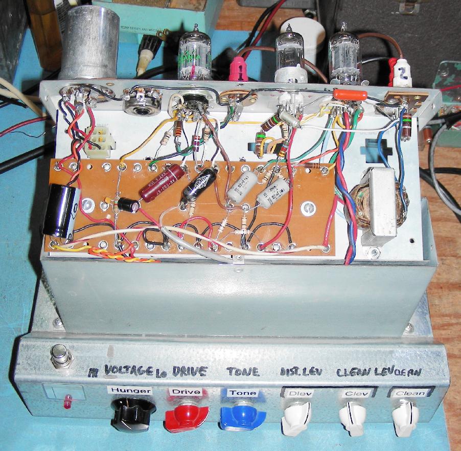
An "M" shaped metal framing section was used for the lower chassis, this allows the AO-42 box to be slightly recessed. The power transformer was mounted on the back side of the chassis top. Be sure to mount the power transformer far from the tubes to prevent picking up hum.
Holes were drilled for the jacks, switches, potentiometers and power cord. A U-shaped metal frame should be constructed to cover the bottom and sides of the chassis. The 1/4" jacks and output level control are located on the back of the lower chassis. One of the dual RCA jacks was drilled out of the AO-42 chassis and the hole was filed out to allow the installation of the 7 pin 6C4 socket. The filament wiring on the Hammond boxes can be re-used. The original components on the circuit board can be unsoldered and the board can be re-used for the new circuitry.
The rectifier circuits and first high voltage capacitor are mounted under the lower chassis. In this build, the power transformer is actually two parts, a small high voltage transformer and a 6.3V filament transformer which were both removed from old equipment. A Hammond P-T269EX transformer is roughly equivalent, these can be purchased new from Antique Electronic Supply. Similar transformers include the Hammond P-T261C6, P-T261E6, P-T261G6 and P-T261X6, the E6 model would be a good first choice. The maximum B+ current draw for this circuit is only 5mA, so any transformer with a current rating of equal or higher than that should work. The 220 ohm, 1W resistor may need to be adjusted in value to produce a B+1 voltage of around 250V.
The output transformer used in this version of the circuit is an EL1254 push-pull Universal Output type. A transformer with a 10K ohm center tapped primary and an 8 ohm secondary (or similar) should also work. The Hammond P-T125A or P-T291 would probably sound good in this circuit, but they tend to be expensive. It should be possible to use an inexpensive 5VAC or 6.3VAC split-bobbin filament transformer with the dual 120VAC primaries wired for 240V center-tapped as the output transformer. When using other transformers, the value of the 15 ohm load resistor may need to be adjusted for the best sound. If you build the circuit and it oscillates, swap the two secondary winding wires on the output transformer.
Plug an electric guitar or other musical device into the input, plug the output into an amplifier or mixing board. Turn the guitar's volume control up high for maximum drive. Use the foot switch to select between the clean and distorted channels. Set the Starvation Voltage and Distortion Drive controls to the midpoint, play your instrument and adjust both controls for the best sound. Increasing the starvation control causes more compression. Adjust the Clean mix and Distortion mix for the desired distortion sound. Adjust the Clean signal control for similar levels on both channels. Adjust the Output Level control so your amp's volume is around the level with the guitar plugged in directly to the amp.
One feature that the Fuzznikator is missing is an indicator which shows whether the clean or distortion channel is in use. It would be relatively easy to change the foot switch to a DPDT type and use the second half of the switch to select between two LEDs. An alternate solution would be to use a SPST switch to control a small DPDT relay and use the relay contacts to select the outputs and LEDs.
Brian White from UMass in Boston has extended the original Fuzznikator circuit by adding a spring reverb and associated driver circuitry. Take a look at his schematic and the photo of his prototype.
Back to FC's Music Circuits page.