(C) 2023 G. Forrest Cook
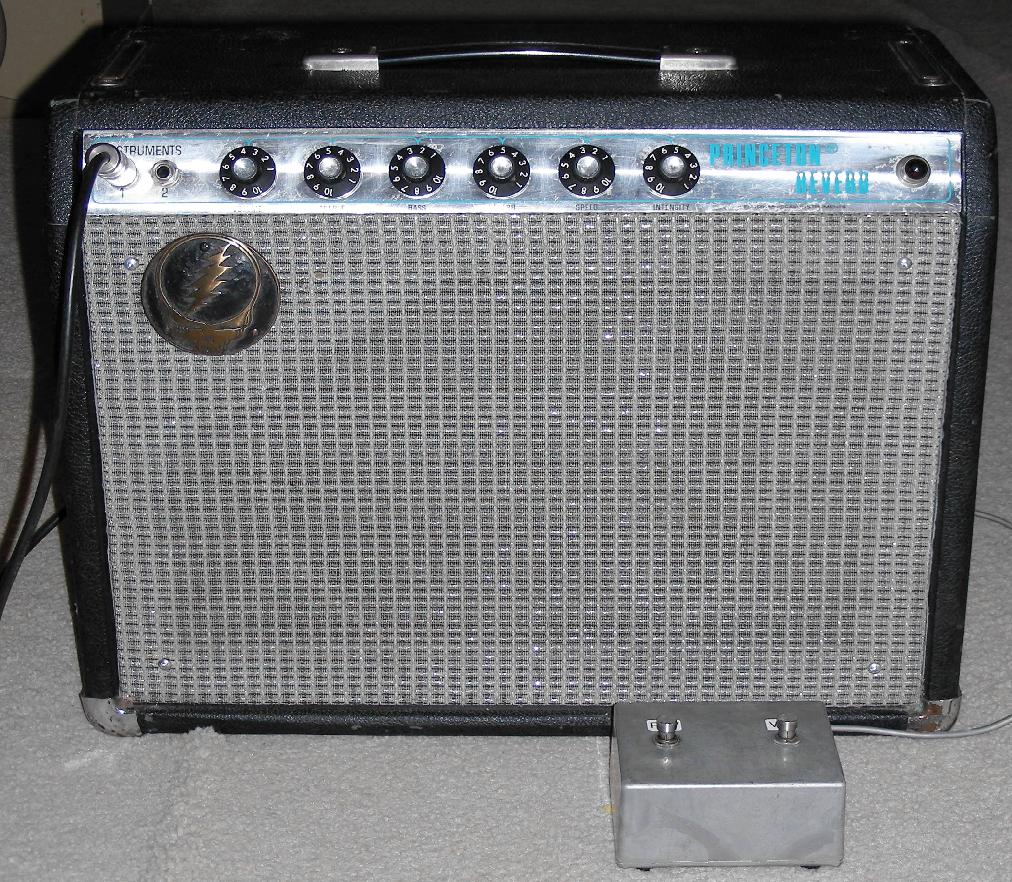
Front view of modified 1972 Fender Princeton Reverb amp.
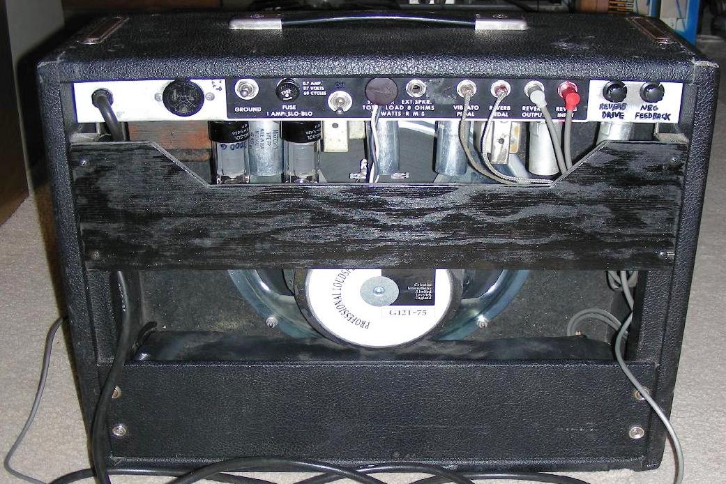
Rear view of modified 1972 Fender Princeton Reverb amp.
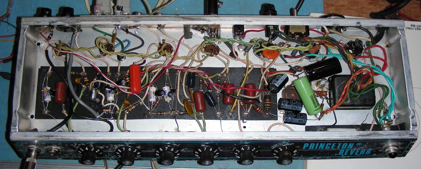
Modified 1972 Fender Princeton Reverb amp chassis.
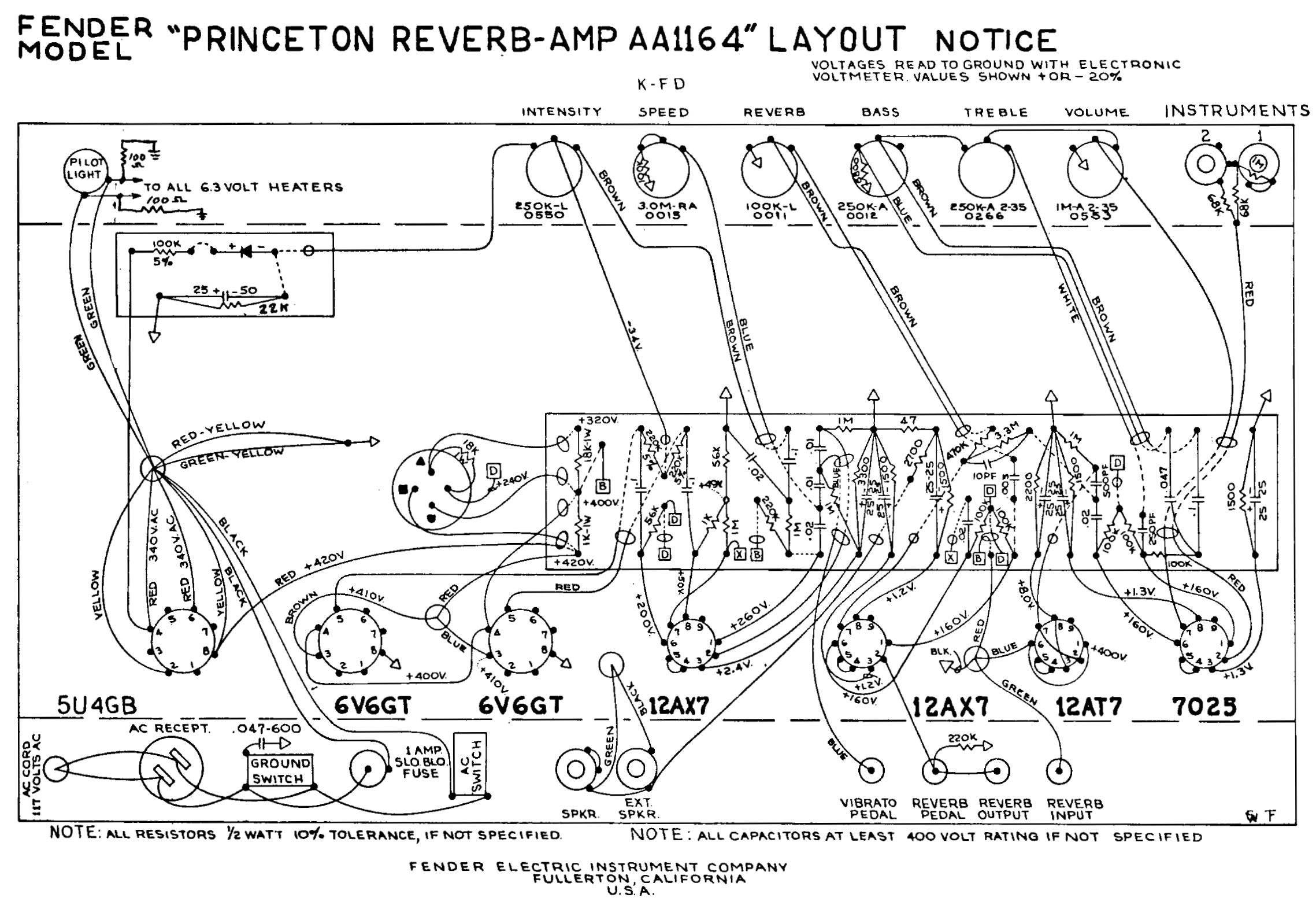
The Fender Princeton Reverb (PR) is a classic guitar amplifier that has a reputation for being a real player's amp. It is small and relatively lightweight but includes both the reverb and vibrato (actually tremolo) effects that were found in the larger and more powerful Fender amps of the same vintage.
This article describes a number of modification that were made to a 1972 PR amp (AA1164 schematic) to restore it to its original functionality followed by the addition of a number of hot-rod features. The most significant change involved replacing the 10 inch speaker with a 12 inch unit. Other changes included adding an adjustable negative feedback (gain) control, an adjustable reverb send control, a B+ standby switch, a line voltage buck circuit, and an adjustable power tube bias control. A few parts were also changed to customize the amp's reverb frequency response.
It should be noted that any non-reversible modifications made to a classic amplifier can devalue the amp in the eyes of a collector. That said, all of the changes made were done with the goal of making the amp a really versatile platform for playing an electric guitar.
This is a fairly high-level project. It takes advanced technician skills to deconstruct and reconstruct the circuitry in guitar amplifiers. Also, there are plenty of lethal high voltages inside of this amp including 120 VAC, 420VDC and 680VAC. The project should only be taken on by someone who has experience working with high voltage circuitry. The power cord should always be unplugged when working on the amp. The circuitry will eventually discharge the capacitors when power is turned off, but it is always a good idea to short out the electrolytic capacitors before working on the amp.
If possible, test all of the tubes with a Gm-reading tube tester and write the readings on the tube sides with a sharpie pen. If you don't have a tube tester available, you can buy a few new tubes and swap them with the original tubes to see if anything changes. It is a good idea to install a pair of matched 6V6 power tubes, these can be purchased new.
When removing the amp chassis from the case, be sure to disconnect the pedal and reverb wires and unscrew the power cable clamp. The amp chassis can be removed from the case and placed on the work bench at this point. Be sure to prop up the chassis with wood blocks so that it does not rest on any of the vacuum tubes.
It is very useful to build or buy a set of male to female extension cables for the speaker cable and the two reverb cables. These allow the amp to be fully tested while it is out of the cabinet.
A number of steps were taken to clean up the amp. All of the knobs were removed and soaked in detergent then the edges were gently cleaned with a toothbrush and detergent, being careful not to remove any lettering. The front panel was cleaned with a mild detergent solution and the remaining residue was removed with a sponge. If any of the controls don't turn freely, place a drop of oil on the control shaft, only do this for controls with metal shafts. Caig fader lube was sprayed into all of the pots and they were worked back and forth a few times to get rid of scratchy sounds in the audio chain.
The excess solder flux was scraped off of the eyelets and chassis solder points using a dental tool with a sharp tip. All of the high voltage eyelets were cleaned with alcohol and a toothbrush and the remaining residue was mopped up with a tisue. The remaining flux residue and loose solder blobs were removed with a vacuum.
The RCA reverb and pedal jacks and plugs were cleaned to remove oxidation. The reverb/vibrato pedal was missing on this amp, so a new one was built in a small Bud cast aluminum box using on/off stomp switches and Belden 8771 dual-pair shielded wiring.
The plastic Tolex coating on the cabinet was cleaned with a detergent solution to remove accumulated gunk and a few loose sections of Tolex were glued back onto the case using construction adhesive.
Its always a good idea to verify that the fuse is the correct value (1 amp slow-blow), the wrong fuse can destroy the expensive power transformer in the event of a shorted capacitor or other short circuit.
If the amp has an original 2-wire power cord, it should be replaced with a grounded 3-wire cord. An old 2-wire cord can allow the amp's chassis to become hot with 120VAC through various leakage paths, this can produce a deadly shock hazard. It is a good idea to remove the 0.047uF death cap that is located on the ground switch since it is no longer required after installing a 3-wire power cord.
The 3 position ground switch can be converted to an input voltage buck selecting power switch. This frees up the original power switch, which is now available for use as a B+ standby switch. The input voltage buck circuit allows the amp to be run on modern 120VAC or higher line voltages instead of the 115V-117V line voltages that were around when the amp was originally built. The buck circuit keeps the tube filaments and B+ circuits running at the correct voltages.
The hot (black) AC power line should connect to the center pin on the former ground switch. One side of the former ground switch connects to the power transformer primary and one of the 5V filament wires, the other side connects to the remaining 5V filament wire. Measure the 6.3V filament voltage, it should be lower when running with the 5V buck line switched in, if the voltage goes up, swap the two 5V wires.
The number one parts that need replacing on old vacuum tube guitar amplifiers are the electrolytic power supply filter capacitors. The old can capacitor was left in place for visual appeal but all of the wiring was removed from the part. The first capacitor in line was changed to a 100uF/450V part and the following three caps were replaced with 22uF/450V parts. The 100uF cap should only be used if the 5U4 rectifier is changed to solid state diodes, the first cap should be limited to 47uF if the 5U4 is left in place.
The 25uF preamp cathode capacitors may also need to be replaced. Mod brand 25uF caps are a good substitute for this amp. The original caps work at low voltages and their values generally stay within tolerance as they age It is a good idea to disconnect one side of each cap and measure with a capacitance tester to verify their value. Note that the photo above shows some extra 100uF black cathode capacitors across the stock 25uF parts (the white caps). These were added as an experiment, but were removed after they were found to make the amp's response too bassy.
Resistors can mostly be checked in-circuit and tend to drift up in value as they age. Carbon composition resistors that dissipate power and run hot tend to be the most susceptible to changes in value. These include resistors associated with the B+ supply and filter capacitors, and the preamp and phase inverter cathode circuits. It is a good idea to make sure that the 56K phase inverter resistors are fairly close in value to maintain good balance on the output stage. It is not unreasonable to replace every resistor in the amp with modern metal film parts if one is inclined to do the extra work. However, the old adage of: if it ain't broke, don't fix it comes to mind.
The 5U4 rectifier was removed and replaced with a pair of 1N4007 diodes. Beefier (3 Amp) 1N5408 diodes can also be used. The diodes were bridged with 1nF/1KV ceramic disk capacitors, these help to protect the diodes from line voltage spikes. The diode/capacitor sets were soldered to the 5U4 socket pins with the cathodes (white bands) connected together and feeding the B+ line and the anodes connected to the red power transformer leads. The yellow 5V 5U4 filament wires were removed from the 5U4 socket and re-routed to the bucking power switch. Replacing the 5U4 with diodes allows the power transformer to run cooler and it frees up the 5V winding for use as a line voltage buck.
A 68 ohm, 2W resistor was added between the rectifier diode cathodes and the first filter capacitor to reduce the power-on inrush current. The resistor also adds a small amount of rectifier sag that is similar to the sag created by the 5U4 rectifier. The resistor value is not critical, anything from 10 ohms to 100 ohms should work.
The former power switch should be connected between the 68 ohm sag resistor and the 100uF filter capacitor where it can now function as a B+ standby switch.
The first filter capacitor was changed from a 20uF/450V part to a 100uF/450V type to lower the overall power supply hum level. An optional 0.22uF/600V capacitor was added across the 100uF capacitor, this can help to eliminate power line induced high frequency noise on the B+ line.
A 3.3M 1/2W resistor should be added across the last 22uF capacitor in the B+ string. This insures that the capacitors discharge when the amp is powered off when the standby switch is turned off.
A few PR modification suggested by Rob Robinette (see link below) were added to the amp. A pair of 470 ohm 3W resistors were installed between the 6V6 screen grid pins and the screen grid B+ line, these prevent RF oscillations on the power tubes caused by a negative resistance kink that can be seen in the 6V6 screen grid response curve. Also, 1.5K 1/2W grid-stopper resistors were added between the 6V6 control grids and the phase inverter output capacitors, those parts work with the tube's Miller capacitance to form a low-pass filter that prevents RF energy from being fed into the power amp.
An optional but recommended R-C snubber was added across the output transformer's primary winding which is across the 6V6 plates. The snubber consits of a 6.8K 2W resistor in series with a 10nF/2KV capacitor. It is connected across the transformer's blue and brown wires on the 6V6 sockets. This network absorbs RF energy from the 6V6 plate circuit and protects the output transformer from internal arcing.
An adjustable negative feedback potentiometer was added to the power amplifier to act as a variable gain/presence control. The control was mounted on the rear panel of the amp's chassis. Replace the 2.7K NFB resistor that connects to the speaker output with a 1K 1/2W resistor in series with a 10K potentiometer. The gain control changes the amp's punchyness. At low gain settings, the amp is linear and constrained (Jazz sound) and at high gain settings, the amp is loud and punchy (Rock solo sound).
A few changes were made to the V4B phase inverter stage. A 33K grid stopper resistor was added between the phase inverter grid and the preamp stage output capacitor to lower the RF response of the stage.
The capacitor between the V3B preamp stage and the V4B phase inverter is labeled 0.02uF on the schematic but there was an 0.008uF part in this amp. This capacitor affects the bass response of the amp. It was chaned to a 10nF (0.01uF) capacitor to give the amp slightly more bass response, which works well with the larger speaker. This value can be adjusted according to your individual taste.
An adjustable 6V6 bias control was added to the amp. This involved removing the 22K fixed resistor from across the bias filter capacitor and replacing it with a 20K potentiometer in series with a 15K 1/2W resistor.
There was a slight difference in this amp compared to the AA1164 schematic, the bias fiter capacitor was an 80uF/75V part instead of the 25uF/50V part. This capacitor should be replaced along with the other power supply electrolytic caps. The capacitor should be changed to a 100uF/63V or 220uF/63V part, the larger capacitor reduces the low-level hum that shows up in the 6V6 power amp stage.
Two 1 ohm, 1W resistors were added between the 6V6 cathodes and ground, these allow the cathode current to be measured while adjusting the bias pot. Idle cathode currents can be determined by ohm's law, current equals voltage divided by resistance (1 ohms). Since each resistor is 1 ohms, the current is the same as the voltage. If the two 6V6 tubes are well matched, the idle bias currents should be similar. The two 6V6 tubes were set to a bias of around 20mA each, or 0.02V across the 1 ohm resistors. Typical bias values range from 10mA (cool) to 35mA (hot and higher gain). I like to bias the tubes at around 15-20 mA which keeps them cool and gives them a longer life. Set the bias higher if you want a bit more output power.
The reverb sound in the stock PR amp is very heavily driven and twangy, a number of changes were made to soften this sound up a bit.
The fixed reverb drive was changed with the addition of a variable reverb send (dwell) control. The dwell control was mounted on the rear panel of the amp's chassis. The 1M grid bias resistor on V2 was removed and was replaced with a 500K (aud) pot in series with a 330K 1/2W resistor to ground. The wiper of the pot feeds the V2 grids. The 500pF disk capacitor feeding the V2 grid was replaced with a 1500pF polystyrene capacitor, the larger value improves the reverb's bass response. This capacitor can be adjusted to taste.
The reverb driver (V2) cathode resistor was changed from 2.2K to 3.3K, this lowers the gain of the stage a bit and allows the tube to run cooler, which will increase its life.
A 330pF silver mica capacitor was added across the reverb return jack to roll off some of the harsher high frequency reverb sounds, this value can also be adjusted to taste.
The original Fender 10" speaker in this amp was scratchy sounding due to an overheated voice coil. The speaker was removed from the amp cabinet and was replaced with a 12" 8 ohm Celestion G12T-75 speaker. One may speculate that Fender used the smaller speaker in the Princeton Reverb so that it did not compete with their larger amps such as the Deluxe Reverb. You may want to connect the amp to an external 12" speaker in a cabinet before doing the 12" speaker mod to make sure that you like the sound. The 10" speaker plays a significant role in the original amp's sound and the 12" speaker makes the amp heavier and louder. I have no regrets on doing this mod to my PR amp.
Many other boutique guitar speakers could also be used, just be sure that the speaker has an 8 ohm impedance and is rated for 20 Watts or more. Upgrading the speaker involved removing the speaker mounting board from the amp, removing the grille cloth, measuring and marking the location of the new speaker and cutting the larger hole with a jigsaw. Be sure that the larger speaker hole is located so that new speaker does not interfere with the chassis and reverb tank before cutting it out. Four speaker mounting holes were marked and drilled out. It is a good idea to round the front side of the new speaker hole with a quarter-round router bit and paint the edges of the hole black. Re-attach the grille cloth and screw the modified mounting board to the amp.
The original upper rear speaker baffle plate was missing from the amp so a new plate was cut out of 3/8" plywood and painted black. Four screw holes were pre-drilled and countersunk in the baffle plate to prevent cracking around the screws. The new plate was installed on the back of the amp.
The Fender logo was missing on this amp, so I modified a heavy bronze Steal Your Face belt buckle and attached it to the front of the amp with three screws.
Keep in mind that the voltages shown on the schematic can be different from the actual voltages in the circuit, scale everything by the difference between the expected main B+ voltage and the actual B+ voltage. The buck mode on the power switch will also change the measured voltages. Measure the 6.3VAC filament voltage, it should generally be between 6.1VAC and 6.5VAC for the longest tube life. Compare the preamp plate and cathode voltages to the values shown in the schematic and be sure to compensate for different B+ values. If the voltages are way off, it may be an indication of a weak tube or resistors that are out of tolerance.
The amp's output power can be measured by substituting an 8 ohm 20W resistor for the speaker and injecting a 500 Hz sine wave into the amp's input. Monitor the signal across the resistor with an oscilloscope. Adjust the signal generator level and input volume level to the highest point below where distortion becomes visible on the scope. The gain control should be centered and the tone controls should be adjusted for the cleanest sine wave on the scope. It's a good idea to limit the time that this test is done since the amp is running at its full-bore output and the output tubes will get quite hot.
The amp's output power can be found by using the formula: Wrms = (Vp-p/2.83)**2 / 8 ohms. Plug the un-distorted peak-to-peak voltage as measured on the scope into the formula. If the amp is operating normally, the output power should be a bit lower than 18 Watts. With a line voltage of 120V and the power switch set to the buck position, this amp produced 30VPP undistorted, or 14W. With the switch in the non-buck position, the amp produced 35VPP undistorted, or 19W.
This is a very fun amp to play through. The straightforward signal path can produce a very clean sound and the amp overdrives nicely. The new reverb send and gain controls give the amp a lot more variablility in the sounds that it can produce compared to the stock configuration. The 12" speaker greatly improves the bass response and overall loudness of the amp.
The vibrato (tremolo) sound is a bit different than other Fender amps from the same period due to the use of power tube bias modulation instead of the more common light-variable resistor. An interesting effect of this type of tremolo is that the blue glow coming from the 6V6 tubes modulates with the tremolo speed and intensity, this is best observed in a dark room.
Back to FC's Music Circuits page.