(C) 2022, G. Forrest Cook
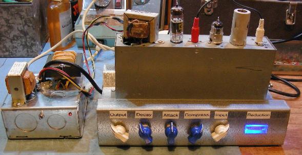
Front of the Squasherator Compressor V1 and external power supply.
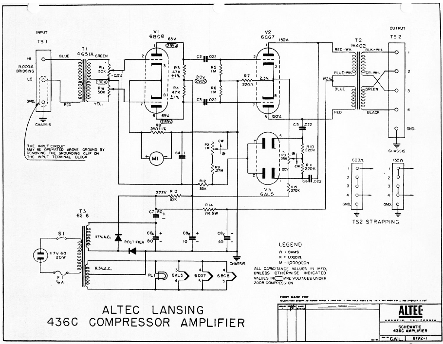
This project involves the conversion of a Hammond AO-42 organ percussion unit into a stand-alone audio compressor which is suitable for use with microphones, electric guitars and keyboards. The circuit is based on the classic Altec 436c compressor. Compressors can be an important tool for making audio recordings. The Squasherator can also be used with a microphone preamp to feed audio to Ham radio SSB and AM transmitters and micro-power AM transmitters such as the AM Chickadee. The squasherator is a fairly high-fidelity device, it compresses the peaks without making major changes to the character of the audio.
The Squasherator name comes from the circuit's ability to squash loud audio peaks down while passing quieter sounds with little attenuation. It is also the third of my vacuum tube effect projects, following in the footsteps of the FuzzniKator Tube Distortion/Preamp effect and the Liquidator Tube Phaser/Chorus effect. All three devices were built with similar chassis assemblies and can be connected in a chain.
If the Squasherator is to be used as a microphone compressor, it will be necessary to amplify the mic with a preamp circuit such as one channel of this Stereo Microphone Preamp.
Builders should have appropriate technical and metal working skills when attemping to re-create this project. A chassis and power supply with input and output jacks, power input, knobs and switches will need to be constructed. The Hammond AO-42 chassis is completely optional, your author had a few of them lying around waiting to be used for new tube projects. Used Hammond AO-42 percussion units can often be purchased for good prices on eBay.
This circuit uses high voltages including 120 VAC and 270 VDC. The project should only be taken on by someone who has experience working with high voltage circuitry. The power should always be removed when working on the phaser. The circuitry is designed to discharge the capacitors when power is removed, but it's always a good idea to short out the electrolytic capacitors before working on the circuitry.
AC Power Input - grounded 120VAC
Input - 10K impedance line-level
Output - 1K impedance line-level
On/Off (on the power supply)
Input Level
Compression Ratio
Attack Rate
Decay Rate
Time Constant Select
Output Level
Reduction Level Meter
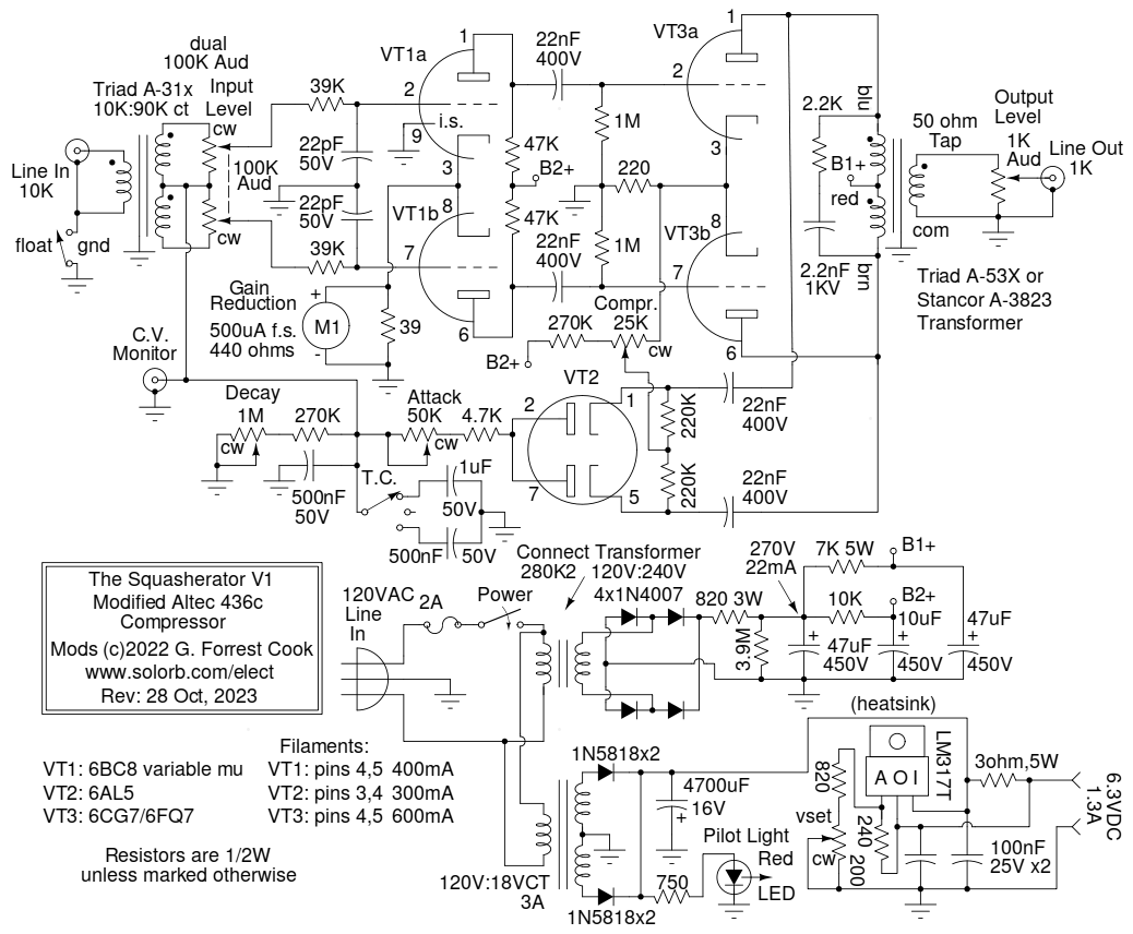
The signal path in the Altec compressor circuit involves a push-pull 6BC8 variable-gain input stage feeding a push-pull fixed-gain 6CG7 output stage. The input and output transformers convert single-ended signals to and from the push-pull signals used in the circuit. The push-pull circuit is used to cancel out the common-mode DC gain-control signal from the signal path. The 6BC8 dual-triode is a variable mu type which has a grid that is wound with a variable spacing across its length. This allows changes in the grid bias to vary the gain of the triodes by modifying the width of the electron beams inside of the tube.
The output signal is tapped off of the 6CG7 plate circuits and is fed to a 6AL5 dual-diode which rectifies the two signal phases to produce a DC voltage that is proportional to the signal amplitude. The rectified DC voltage is fed to an R-C low-pass circuit which removes the higher frequency components to produce an average volume-level signal. The attack, decay and time constant characteristics of the low-pass circuit can be adjusted with two variable resistors and a selectable capacitance. The compression control sets the DC bias level of the rectifier circuit which in turn sets the static DC bias level of the 6BC8 triodes.
The R-C time constant can be set to three different ranges depending on which capacitors are selected. Capacitances of 500nF, 1uF and 1.5uF can be selected with the switch. An inexpensive center-off spdt toggle switch was used to select the capacitors, a rotary switch could also be used here and would allow even more capacitance values to be selected.
The Reduction Level Meter circuit is uses a 500uA meter across a current shunt resistor to measure the cathode current through the 6BC8 triodes.
The original Altec power transformer is not easily found, and does not provide enough voltage to run a regulated DC filament circuit used here. The Squasherator power supply uses two separate transformers. The high-voltage transformer is a 120V:240V (1:2 ratio) part that can provide around 40mA of current under load. The high voltage AC is rectified to DC with a 1N4007 bridge rectifier. The rectified DC is reduced to 270V with an 820 ohm dropping resistor and filtered with a 47uF capacitor. This resistor value may need to be adjusted if you use a different transformer. The two B+ voltages are further dropped and filtered with additional resistors and capacitors. Another way to produce 240VAC is to use a pair of modern split-bobbin transformers, see this circuit for an example.
The tube filaments are powered with 6.3VDC power instead of the 6.3VAC used in the original Altec circuit. Powering the filaments with AC will introduce a low level of hum in the output signal. Running the filaments on DC was shown to reduce the hum level to nearly inaudible levels. DC-powered filaments are not required, but are recommended if you intend to use the Squasherator for studio/recording work.
The filament transformer is an 18VAC center-tapped 3A unit sourced from your author's junk-box. The transformer's AC output is rectified with two pairs of paralleled 1N5818 Schottky diodes and filtered to around 9VDC with a 4700uF capacitor. The DC is regulated to 6.3VDC using an LM317T adjustable regulator that is mounted on a TO-220 heat sink. The regulator is rated at 1.5A and runs quite hot at the 1.3A filament current, so a 3 ohm cheater resistor was added across the regulator's input and output terminals to lower the current through the regulator. Note that the filament voltage will rise above 6.3V if any of the tubes are removed. A larger heat sink for the LM317T or a higher-current regulator such as an LM338T with a larger heat sink might be a better solution.
The Squasherator circuit differs from the Altec 436c circuit in a number of ways. The input and output transformers used in the Altec are difficult or impossible to find and similar modern boutique transformers tend to be very expensive. A Triad A31x interstage transformer was used for the input side and a Stancor A-3823 8W universal output transformer was used for the output side. Both of these parts can be replaced with similar transformers.
The output transformer should have a high impedance center-tapped primary and a medium impedance secondary, between 50 and 600 ohms. The Stancor A-3823 8W universal output transformer has taps at 2, 4, 8, 16 and about 50 ohms. The 50 ohm tap was used for the output, use pins 1 and 6. A Triad A-53X transformer which has 600, 250 and 50 ohm output impedance windings has also been tested in this circuit using its 50 ohm output winding. The A-53X has a better impedance match to the output tubes compared to the A-3823 and produces a higer output level. The A-53X is the recommended transformer for this circuit, if you can find one. Another output transformer that could be used in this circuit is the Stancor A-3856 4W universal output transformer. Like the A-3823, the A-3856 model also has a 50 ohm output tap.
The Gain Reduction meter was a part from my collection of used meters, most 500uA meters should work here. Different meters may need to have the value of the 39 ohm shunt resistor adjusted so that the meter shows its maximum reading with no input signal. This resistor sets the operating current for the 6BC8, so the value should not be changed much. If the meter needs to be made less sensitive, a resistor in series with the meter can be used. A blue LED pilot light with a 470 ohm current limiting resistor (not shown in the schematic) was installed inside of the meter to act as a pilot light, it is powered by the 6.3VDC supply.
The 6BC8 VHF dual triode had a tendency to oscillate at radio frequencies when large input signals were present. This problem was fixed by adding a 39K grid stopper resistor and a 22pF grid to ground capacitor to each triode section. Similarly, the 6CG7 output circuit also had RF oscillation issues. An RC snubber consisting of a 2.2nF capacitor in series with a 2.2K resistor was added across the output transformer's primary to eliminate these oscillations.
A variable attack control was added to give the circuit more control over the compression envelope. The decay circuit was moved to the capacitor side of the attack resistor so that it does not interact as much with the variable attack control. A switch (labeled T.C) selects three different capacitor combinations to provide three time constant ranges.
Finally, the power supply in the Squasherator was built with available parts, the HV side should be able to provide 270V under a load of 22mA. The Filament supply was changed from 6.3VAC to regulated 6.3VDC as described above, this change lowers the background hum level of the circuit.
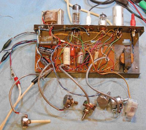
Inside of the Squasherator V1 during the prototyping stage
The AO-42 box provides a chassis with two tube sockets and a plug board for connecting most of the parts. The AO-42 also has five RCA jacks built into the top, some of which can be used for the audio input and output connections. If you choose to build this circuit into an AO-42 chassis, it will be necessary to unsolder most of the original wiring on the tube sockets. All of the parts should be removed from the plug board and the board should be taken out and cleaned with alcohol and/or laundry detergent to remove old solder flux and dirt. Be sure to remove any left-over wire pieces from the solder pots on the board so they don't push through and short to the metal case.
The Hammond AO-42 chassis was modified (see above photo). The original electrolytic can capacitor was removed from the chassis and the output transformer was mounted over the capacitor hole. The input transformer was mounted inside of the chassis. The center dual RCA jack was removed and the resulting hole was filed out and drilled to fit a 7 pin tube socket for the 6AL5 dual diode. The tube lineup is: VT3, VT2 and VT1 (left to right). The VT1 socket has supports for a tube shield, the shield should be installed since it helps prevent noise pickup by the 6BC8 tube.
An "M" shaped metal framing section was used for the lower chassis, this allows the AO-42 box to be slightly recessed. Holes were drilled and filed in the frame for the potentiometers and gain reduction meter. A U-shaped metal frame should be constructed to cover the bottom and sides of the chassis.
The filament wiring was preserved, but was partially re-routed to support the different tube types compared to the original circuit.
The three RCA jacks on the AO-42 box were rewired to provide the input, output and control voltage monitor connections. The rest of the wiring was run through holes between the lower chassis and the AO-42 box. Be sure to leave the wires long enough to allow the AO-42 box to be opened. The B+, Ground and 6.3VDC filament voltages were routed through the rectangular plastic connector on the outside of the AO-42 box.
The power supply was built into an external 4"x4"x2-1/2" electrical utility box. The power cord and DC output wiring was secured to the box with a 1/2" Romex cable clamp.
Using the Squasherator is fairly straightforward. Line-level inputs can be fed directly to the input connection and line-level outputs can be taken from the output connection. The input level control should be adjusted so that the meter moves when the compression control is in the middle of its range. The meter should not dip to the bottom of its range or distortion will occur. The output level control should be adjusted so that the following stage is fed with enough signal to overcome its noise floor, but not so much that it becomes overloaded.
Adjust the compression control and input level control for the desired amount of gain reduction. The attack, decay and time constant controls can be adjusted for the desired response. Listen to the output for the best sounding settings on all of the controls, this will vary depending on the type of audio that is run through the compressor.
Low-level signal sources such as microphones and electric guitars will require using a preamplifier ahead of the Squasherator. One channel of the Stereo Microphone Preamp was tested with the Squasherator and it had plenty of gain for amplifying dynamic microphones. The Fuzznikator was used as a preamp for an electric guitar and also produced enough gain to activate the compressor. Note that the float/ground switch on the input circuit should be tested in both settings, use the setting that produces the least hum in the output signal.
The power supply unit should be located away from the Squasherator. It is a good idea monitor the output signal for minimum hum while moving the power supply around. The input transformer and 6BC8 tube are sensitive to magnetic hum-producing sources such as power transformers in other equipment.
If possible, it is best to use new-old-stock (NOS) tubes for this project. All of the tubes used here are available on eBay for reasonable prices. If you have access to multiple tubes and a tube tester, it is a good idea to select 6BC8 and 6CG7 tubes which have similar gain characteristics between the two triode sections. Balanced tubes will help with rejection of the common-mode gain control voltage.
The only critical tube in this circuit is the 6BC8 variable mu dual triode, also known as a semi-remote cutoff dual triode. 6BZ8 tubes are very similar to the 6BC8 and have the same pinouts. The 6BS8 is also similar, but is not a semi-remote cutoff tube so it should not be used in this circuit. 4BC8 and 4BZ8 tubes are also equivalent to 6BC8 tubes, but with 4.2V/600mA filament requirements. The 6386 tube is another variable-mu dual triode, but has a different pinout. It is a special-quality military tube that is rare and very expensive.
The 6CG7/6FQ7 tube is relatively common and is not too expensive. A 6SN7 tube is similar to the 6CG7/6FQ7, but comes in an octal package. Vintage 6SN7 tubes are in high demand by Hi-Fi enthusiasts and tend to be pricey. There are companies such as JJ that manufacture new 6SN7 tubes.
If the builder is a fan of octal tubes, the 6AL5 dual diode could probably be replaced with a 6H6 tube. The 6H6 comes in a metal envelope and the 6H6GT comes in a glass envelope. The 6AL5 has a higher maximum plate current rating of 9mA compared to 2mA for the 6H6, so the 6H6 may perform differently in this circuit.
Back to FC's Music Circuits page.