(C) 2023, G. Forrest Cook
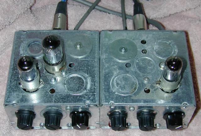
Top-Front view of the mic preamp with tube shields removed.
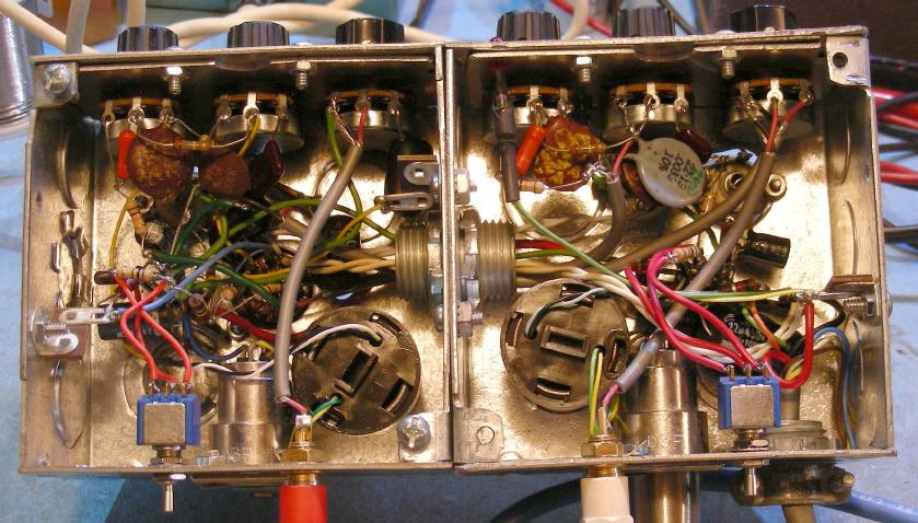
Bottom view of the mic preamp, the blue gain switches are on the back.
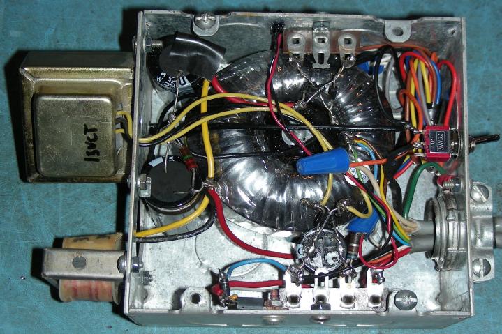
View of the mic preamp power supply, the toroid is the 160VAC transformer.
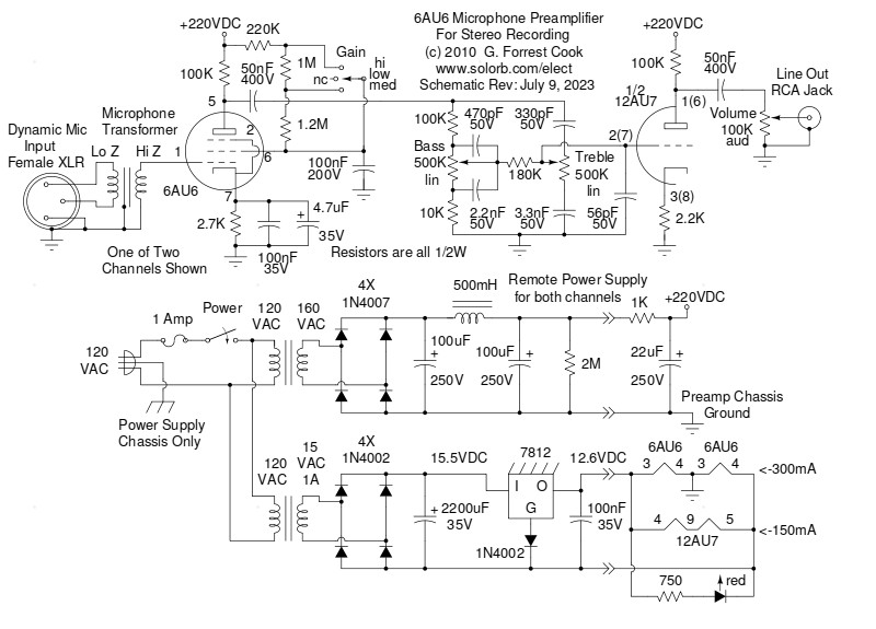
Vacuum Tube Stereo Mic Preamp schematic.
This two channel microphone preamplifier is designed to interface a pair of dynamic microphones directly to a line-level input on a tape recorder, mixing board or a computer sound card. The circuit is configured like a mixing board input strip so that each microphone channel has a gain switch, bass and treble cut/boost controls and an output level control. With a larger power supply, this preamp could be built for more than two channels and would be suitable for use as the input side of a vacuum tube (valve) mixing board.
The project was inspired by your author's attempts to record live audio using various small solid-state mixing boards with built-in mic preamps. The preamps all produced high levels of hiss and a quieter mic preamp was desired. The hiss problem is multiplied when making a multi-track audio recording since each new track adds to the combined hiss level. This preamp can be used to feed a mixing board's line-level inputs.
A number of different tricks were used in this project in order to keep the noise level low and the 60 cycle hum to a minimum. These include powering the tube filaments with DC, isolating the power supply ground from the AC ground, having plenty of filtering on the B+ line and isolating the microphone input with a transformer. The power supply circuitry was also located in a remote box to eliminate pickup of hum from the power supply transformers and AC wiring. These tricks work together to produce a microphone preamp with very low hum.
This project uses potentially dangerous high voltages including 120 VAC, 160 VAC and 220 VDC. The project should only be attempted by someone who has experience working with high voltage circuitry. The power cord should always be unplugged when working on the preamp. The circuitry is designed to discharge the capacitors when power is removed, but it's always a good idea to short out the electrolytic capacitors before working on the preamp.
Power Input - grounded 120 VAC
Microphone Inputs - Low Impedance Dynamic Mics
Line Outputs - 50K, 5V P-P (approx)
Power On/Off
Gain (3 levels, 2 channels)
Bass (2 channels)
Treble (2 channels)
Volume (2 channels)
The microphone signal is sent via a balanced and shielded mic cable to a female XLR jack which connects to the microphone transformer inside of the preamp box. The mic transformer changes the low impedance balanced microphone signal into a high impedance unbalanced signal for driving the 6AU6 control grid (pin 1).
The 6AU6 sharp-cutoff pentode is wired as a high gain class-A amplifier. The cathode circuit has a 4.7uF bypass capacitor in parallel with a 100nF capacitor to provide a wide signal bandwidth. The cathode bias is set by the 2.7K resistor. The screen grid (pin 6) is AC-bypassed with a 100nF capacitor.
The gain of the 6AU6 stage can be set to three levels by varying the screen grid's bias current. An SPDT center-off toggle switch selects a screen resistance of 220K, 1.22M or 2.42M by selecting taps in a resistor ladder. A 2M or 2.5M potentiometer (if you can find one) in series with a 220K resistor could be substituted for the variable gain switch and resistors to provide continuously variable gain, however a dirty pot can be an additional source of noise.
The output of the 6AU6 pentode stage is DC-blocked with a 50nF capacitor and is sent to a Baxandall tone stack. The output of the tone stack is fed to one 12AU7 triode section, wired as a class A amplifier. The 12AU7 stage acts as a buffer/recovery stage for the tone stack and provides drive for the preamp's output.
A few modifications were made to this circuit in 2023 to improve the ability of the tone stack to reach a relatively flat response across the 20-20Khz audio range. The first mod involved changing the 6AU6 cathode capacitor from 100uF to 4.7uF to eliminate excessive bass respone. If a bass-boost function is desired, it would be easy to add an extra 10uF capacitor that could be switched across the 4.7uF cap. The capacitor on the low side of the bass control was changed from 4.7nF to 2.2nF, this raised up the response of a mid-low frequency dip. Finally, a 56pF capacitor was added across the 12AU7 grid to get rid of a rise in the response at frequencies above 20Khz.
The power supply was built in a separate enclosure with a four foot power line, this keeps the power transformers from introducing hum into the preamp circuitry. The high voltage supply uses a surplus 160VAC toroidal transformer to supply AC to a bridge rectifier and pi-network ripple filter. The toroid is not required, it was in my parts collection. The 500mH choke and large-value 100uF filter capacitors in the pi-network produce a B+ voltage with very little ripple, this minimizes the output hum. A 1K/22 uF RC filter is mounted in the preamp box to further filter the high voltage DC and remove any noise picked up in the remote power supply cable.
The filament supply produces a floating 12.7VDC source. The 15VAC from the filament transformer is rectified by a bridge rectifier and filtered by a 2200uF capacitor to provide around 15.5VDC for the 7812 voltage regulator IC. The 7812 negative voltage reference is raised around 0.6V above 0V via the 1N4002 diode, this makes the regulator produce 12.6V for the tube filaments. Resistance from the remote power supply wiring may drop the filament voltage a small amount. The 7812 regulator should be mounted on an aluminum heat sink, the regultor tab and heat sink should be electrically isolated from the chassis ground. The regulator can also be mounted to the power supply chassis with an insulating spacer and a plastic shoulder washer.
The 12AU7 tube's filament is driven directly from the 12.6V supply, it consumes 150mA of current. The two 6AU6 (6.3V) filaments are wired in series across the 12.6V supply, they consume 300mA of current. Both filament circuits consume 450mA of current, which is well within the 7812 regulator's maximum current capacity of 1 Amp. The ground connection for the filament circuit comes from the center tap between the two 6AU6 tubes, this provided the lowest hum.
The three tubes consume 450 mA of current so the 7812 regulator should be able to power two of these circuits (4 channels) if it is properly heat sinked. A higher-current filament transformer would be required if the circuit is doubled. The 2200uF capacitor on the input side of the 7812 would need to be changed to 4700uF for a double-current filament supply.
The power supply components were mounted on a 5"x5" electrical utility box, a standard romex style clamp was used to secure the AC input and DC output cables. One of the transformers and the choke were mounted on the outside of the power supply box. Note that the AC ground is only connected to the power supply box frame and the DC ground is only connected to the preamp box frame. The preamp box gets its external ground connection through the computer or mixing board that it connects to. This configuration will eliminate a hum-producing ground loop.
The preamp components were mounted in a pair of 4"x4" electrical utility boxes, the two boxes were bolted together and holes were punched out between the boxes as a pass-through for the internal wiring. An aluminum plate was fashioned to fit inside of each box, the plates were screwed behind the three knockout holes in each box and were drilled out for the tone and volume controls. Knockout holes were removed from the tops of the boxes to alow mounting the three tube sockets. Knockout holes were also removed for the two XLR jacks. Tube sockets with metal tube shields are recommended for the 6AU6 pentodes, the shields can reduce the pickup of hum and electrical noise.
Solid box-cover plates were used for the bottom of the boxes and stick-on rubber feet were attached to the plates. A number of terminal strips were added inside of the boxes for connecting the various resistors and capacitors. The wiring is somewhat crowded, especially in the box with two tubes. Beginners would be advised to use a larger box.
Most of the parts used in this project came from my junk box. The Strat Monger lists a number of suppliers of vacuum tube parts. eBay is a good place to find tubes, tube sockets, transformers and other parts.
A number of different 6AU6 tubes were tried until a pair with low microphonics was found. There was a significant difference between tubes in a batch of around ten tubes. Luckily, 6AU6 tubes were mass-produced for radios and TVs in the 1950s and 1960s and they are still widely available for low prices.
It is possible to use 12AU6 pentodes instead of 6AU6 pentodes, the two 12AU6 filaments should be wired in parallel with the 12.6V supply and the filament supply ground should be moved to the center tap (pin 9) of the 12AU7 filament. Another possible substitue for the 6AU6 would be an EF-86/6267 pentode, those tubes were specifically designed for audio use.
The transformers shown may be difficult to find, transformers with similar parameters may be substitued. If you can't find a 15V transformer for the filament circuit, a more common 16V unit such as a doorbell transformer can be used. A pair of common split-bobbin transformers can be used for the high voltage supply, see this circuit for an example, the transformers should be set to produce 160VDC when powering the mic preamp.
The microphone input transformer was scavanged from a 1960s vintage Shure M68 solid state microphone preamp, it is similar to a Shure M67 transformer. A single-ended 10K to 4 ohm tube output transformer wired with the mic connected to the speaker leads would probably work as a substitute, but the Shure transformer or a boutique mic to grid transformer would be the better choice.
Connect your microphones to the preamp using good quality shielded mic cables. Connect the output signals to the line-level input of a computer sound card, a tap recorder or a mixing board. Audio should be monitored on the computer or mixing board if possible.
Select Low, Medium or High gain on each of the channels depending on the level of the sound you will be recording. The High gain setting is best for use with acoustic instruments and natural sounds. The Medium and Low gain settings are best for use with amplified instruments and drums. If any distortion is heard in the output, select a lower gain. The gain switch can produce a loud pop in the signal when it is changed, it is a good idea to turn down the output when changing the gain, especially if you are monitoring the signal with headphones.
Set the preamp's tone controls for the most pleasing sound contour and adjust the output levels so that the signal does not overdrive the following audio stage and produce clipping distortion.
A comparison was performed between this preamp and a Behringer Eurorack UB1202 mixer using Shure SM57 mics. One microphone was sent to one of the UB1202 mic inputs and the other was sent through the tube preamp and into another of the UB1202 line inputs. Audio was monitored from the UB1202 headphone circuit. The levels were set for equal headphone volume between the channels. The difference between the two channels was not subtle at all. The hiss coming from the Behringer's preamp was quite noticeable and the tube preamp's hiss was almost undetectable. A lot of audio detail that could be heard on the tube channel was completely obscured by the noise in the Behringer's mic preamp stage. Using the often bogus hi-fi lingo, this preamp really does add a lot of subtle nuances to the sound.
One weakness with this circuit comes from tube microphonics. The 6AU6 is normally used as an RF tube, not an audio tube. The high gain of the 6AU6 makes it produce a lot of microphonics. Tapping on the side of the tubes produces a fair amount of sound and the preamp should never be placed close to a loud sound source such as a guitar amplifier. In environments where loud sound is unavoidable, such as in a room with a drummer, it would advisable to locate the preamp box inside of a padded case for sound shielding. Other pentodes can be used instead of the 6AU6, an EF86 pentode is intended for audio use and should work if the appropriate tube socket pin changes are made.
Back to FC's Music Circuits page.