(C) 2023 G. Forrest Cook
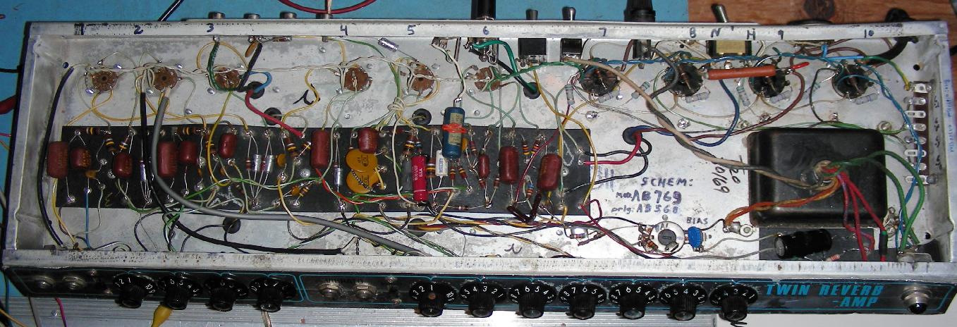
Underside of the modified 1969 Fender Twin Reverb amp chassis, click for larger image.
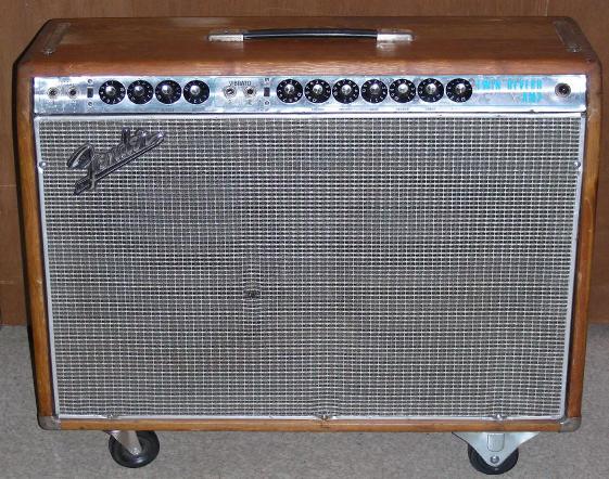
Front view of the 1969 Fender Twin Reverb amp.
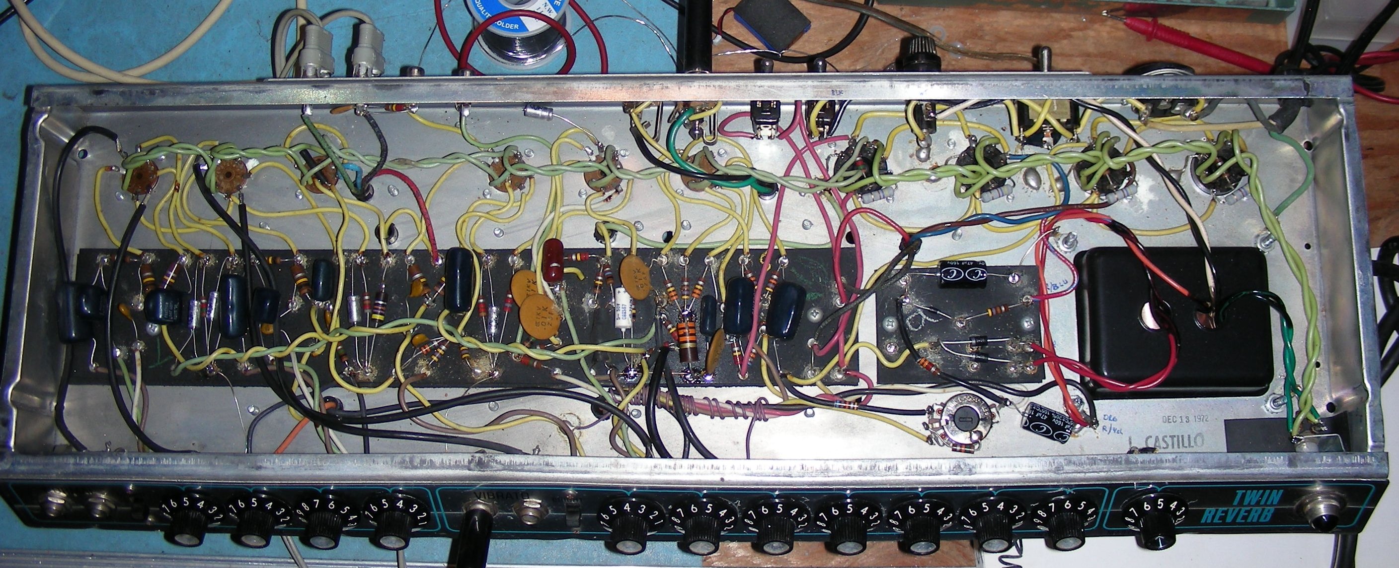
Underside of the modified 1972 Fender Twin Reverb amp chassis, click for larger image.

Front view of the 1972 Fender Twin Reverb amp.
A friend asked me if I could fix his 1972 Fender Twin Reverb amp. After being stored unused for many years, it made popping sounds when it was powered up. I took on the project and was able to get the amp running nicely after doing a fair amount of work. I also happened to own an older 1969 Twin Reverb that I had bought from a friend over ten years ago, that amp was also in need of a lot of work and had been a "someday" project for a long while. After restoring the 1972 Twin, I decided to dig into the 1969 amp and perform some variations on the popular blackfacing mods. This article describes the repairs and changes that were done to both amps to bring them back to a fully operational state.
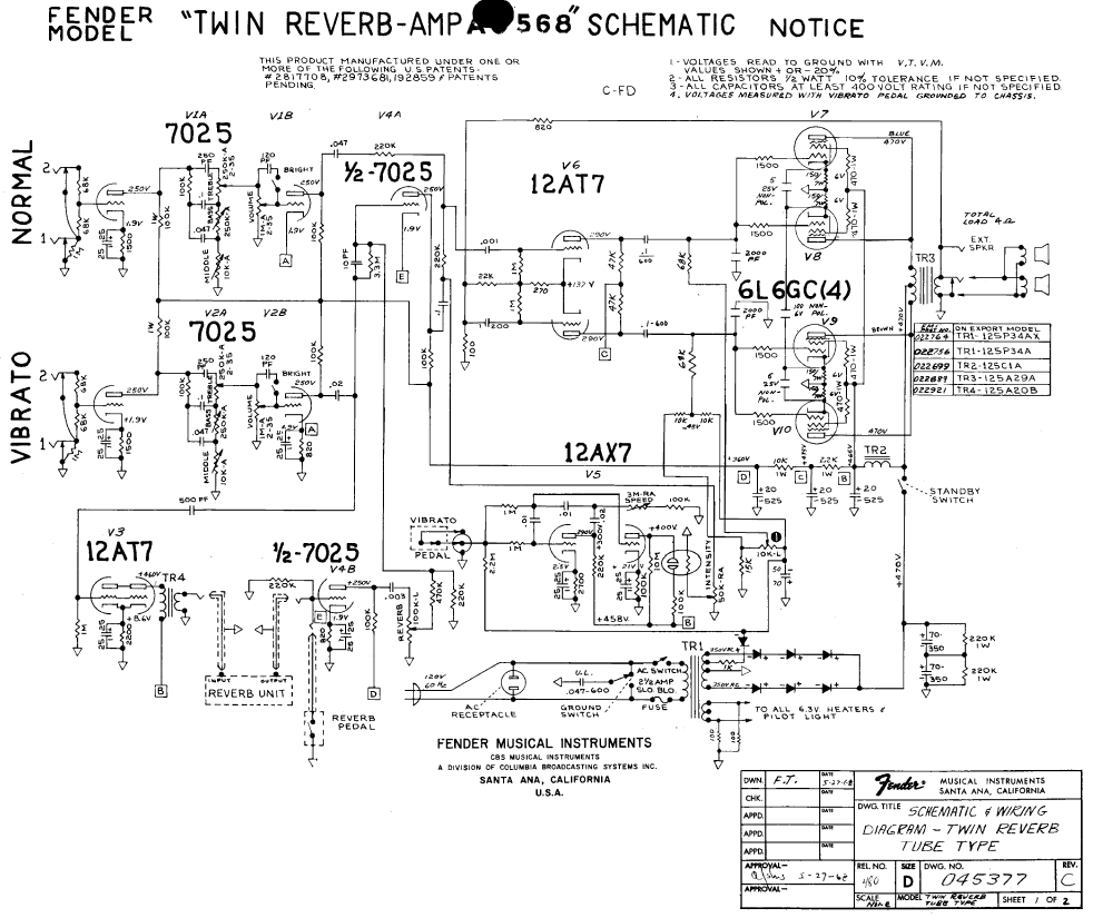
The 1969 Twin was built with the much-derided and short-lived AB568 circuit. It featured the famous 0.002uF tone-deadening capacitors on the power tube grids and a strange combination of fixed and cathode bias on the power tubes. The bias balance circuit on this particular amp was like the circuit in the AB769 version, the balance control shown in the AB568 schematic is odd and possibly a mistake because it only affects one pair of output tubes, not both. The wiring in this amp was fairly sloppy compared to the 1972 Twin. This era of Fender Twins is known to have gone through a lot of changes, not all of which were well documented.
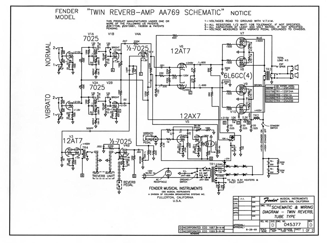
The 1972 Twin had the added master volume control. The closet schematic that I could find was the Delrefugio Amplification version shown in the Resources section below. The wiring in this amp was much cleaner and more organized than the 1969 amp. Despite the various differences, the preamp and power supply circuitry in both amps are much the same, with a few different resistor values in the phase inverter.
My general philosophy is: if it ain't broke don't fix it, with a few exceptions. My repair efforts tend to be aimed at making a fully functional player's amp and not so much at restoring an amp as a museum piece. These projects were mostly a work of techno-love, and may not necessarily be profitable for someone trying to make a living fixing amps. See the video below for another unprofitable but worthwhile repair effort. Many thanks go out to those who have posted a wealth of information and schematics on various Internet guitar amplifier forums and elsewhere.
Late 1960s and early 1970s Fender Twin Reverb amps can still be found for sale at reasonable prices although the prices are likely going to rise, no guarantees. All of the parts used in these amplifiers can still be purchased new, so repairs are relatively straightforward, if somewhat labor intensive. Resistors, capacitor kits and one power transformer used in these restorations were purchased from Antique Electronic Supply.
This is a fairly high-level project. It takes advanced technician skills to deconstruct and reconstruct the circuitry in these amplifiers. Also, there are plenty of lethal high voltages inside of this amp including 120 VAC, 450VDC and and 630VAC. The project should only be taken on by someone who has experience working with high voltage circuitry. The power cord should always be unplugged when working on the amp, the circuitry will discharge the capacitors when power is removed, but it is always a good idea to short out the electrolytic capacitors before working on the amp.
A few easy tasks should be performed before working on a complicated amplifier such as a Twin Reverb. I used a Sharpie pen to label the tube numbers on the bottom edge of the chassis, this saves a lot of time when probing around the circuit. It can also help to label the function of the preamp tubes starting with V2: clean preamp, vib preamp, vib send, vib recovery, vib osc and phase inverter. Print out the schematic(s) and pencil in the tube pin numbers. The left side dual triodes are K:3, G:2 and P:1 while the right side are K:8, G:7 and P:6. The 6L6 pins are: K:8, G:5, Screen:4 and P:3. Pins 1 and 6 on the 6L6 sockets are used as tie points and don't connect to the tube.
Its always a good idea to verify that the fuse is the correct value, the wrong fuse can destroy the expensive power transformer in the event of a shorted capacitor or other short circuit. If the amp has an original 2-wire power cord, it should be replaced with a grounded 3-wire cord. An old 2-wire cord can allow the amp's chassis to become hot with 120VAC through various leakage paths, this can produce a deadly shock hazard. It is a good idea to replace the 0.047uF death cap on the ground switch with a new class X-Y capacitor. A better solution is to just clip out the death cap since it is no longer needed if you are using a 3-wire power cord.
If possible, test all of the tubes with a Gm-reading tube tester and write their gain on the tube sides with a sharpie pen. If you don't have a tube tester available, you can buy a few new tubes and swap them with the original tubes to see if anything changes.
When removing the amp chassis from the case, be sure to disconnect the pedal and reverb wires and unscrew the power cable clamp. It is a good idea to remove the 6L6 that is by the right side of the amp in order to access the two mounting screws. The amp chassis can be removed from the case and placed on the work bench at this point. The power transformer should rest on a piece of 3/4" wood or a small book to keep the chassis weight off of the 6L6 tubes.
It is very useful to build or buy a set of male to female extension cables for the speaker cable and the two reverb cables. These allow the amp to be fully tested while out of the cabinet.
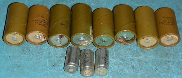
The number one thing to replace on an old amplifier is the electrolytic power supply filter capacitors. There are five such capacitors located under the metallic dog house cover on the top of the chassis. Most of the old brown capacitors on both Twins showed signs of leaking electrolyte and were way beyond their useful life. Capacitor kits were purchased and all of the dog house capacitors were replaced. These caps are all subjected to high voltages which cause them to fail at a high rate.
The four power resistors in the dog house were also ordered from the same company and were all replaced. Four 470K screen grid resistors for the 6L6 tubes were also purchased and installed. All of these resistors were upgraded from the original 1W units to 2W types. After replacing all of the dog house components, it is a good idea to scrape off any flux residue from the plug board to lessen the chance of high voltage arcing.
All of the 25uF cathode capacitors in the preamp stages were replaced with new parts from the capacitor kits. The old white 25uF caps were tested on a capacitor tester and all of them were still within tolerance, but they showed lower Q factors when compared to the new parts. This indicated higher series resistance and possibly leakage. Replacing these caps is just insurance against future failures and it's easy to do. The cathode caps only operate with a few volts across them, which is probably why the original parts were still usable.
Resistors can mostly be checked in-circuit and tend to drift up in value as they age. Resistors that dissipate power tend to be the most susceptible to changing value. These include resistors in the preamp cathode circuits, the preamp plate circuits, various phase inverter resistors, bias supply resistors and vibrato circuit resistors. It is a good idea to make sure that the phase inverter resistors of the same value are fairly close in value to maintain balance.
The power transformer in the 1972 Twin showed signs of overheating, it had dripping black goo and a strong smell, it was also quite rusty. A new Hammond 290FX transformer was purchased and was installed in the chassis. The wire color codes on the new transformer were the same as on the original part, but care should be taken when re-connecting the new wires. Be especially careful not to mix up the wires on the high voltage and bias winding.
The rectifier diodes were replaced in both amps. This in not absolutely necessary, but is a good way to prevent future problems since the original parts are over 50 years old. The two strings of three RCA metal diodes in the high voltage section were replaced with a pair of 1N5408 1KV/3A diodes. The bias supply diode was replaced with a 1N4004 type.
It was necessary to move the 1N5408 diodes to new locations on the plug board since they were shorter than the original string of three diodes. The cathode ends should be soldered together above the board so that a single fatter wire can be fit into the tie point. Double-check the diode polarity, the white stripe goes away from the transformer lead on the high voltage side and toward the transformer lead on the bias supply. Be sure to scrape off the flux residue on the rectifier board to prevent high voltage arcing.
In the 1969 amp, a 1K series resistor between the power transformer and the bias rectifier diode was replaced with a 2.2K resistor, this brings the bias voltage into a more useful range. An overall bias level adjustment was added by inserting a 10K variable resistor between the bias supply filter capacitor and the wiper of the bias balance pot. Hum in the bias supply showed up as ripple on the 6L6 grids and a low-level hum could be heard through the speakers when the amp was idle. The 47uF bias filter supply was replaced with a 330uF/100V capacitor and the hum was eliminated. The vibrato cut-off line that connects to the foot switch via a 2.2M resistor was moved from the bias balance pot to the negative side of the bias supply filter capacitor, this matches the circuit in the AA769 schematic.
The bias circuit in the 1972 amp had two 47uF filter capacitors with a 3.3K resistor between them, which differs from the AA769 schematic and is similar to the Delrefugio circuit below. This amp did not produce any noticeable hum from the bias circuit. A 10K bias trimmer resistor should be added in series with the 3.3K resistor to adjust the overall bias level. It may be necessary to adjust the value of the 2K resistor that is in series with the bias supply diode to set the range of the bias trimmer.
On the 1969 amp, the 6L6 cathodes were connected to ground via 150 ohm 7W resistors and were bypassed with 5uF non-polar capacitors between cathode pairs. A 100uF non-polar capacitor was connected between one side of the opposite-phase tube pairs. These resistors and capacitors were all removed.
The 6L6 cathodes were all connected to ground through 5.1 ohm 2W resistors. The resistors were added to allow monitoring the individual 6L6 cathode currents. The resistors also add a tiny amount of negative feedback to each tube, but this is insignificant. The original wires between the cathodes and the non-polar capacitors were left in place and the old capacitor terminal strip is now used as a set of convenient test-points for measuring the tube idle currents.
The 1972 amp came with all of its 6L6 cathodes tied to ground, it should be possible to add the current-monitoring resistors but this has not been tried.
Fender Twin amps of this vintage produced a ticking sound that was caused by the firing of the neon bulb in the vibrato circuit. Note that this is really a tremolo effect, not a true vibrato like in a Magnatone amp. Both of these amps had the ticking problem, it was most audible with the vibrato set to half intensity and the vibrato channel's input volume turned down.
A number of discussons about this problem were found on the Internet, along with several recommended modifications which were performed to eliminate the problem.
The vibrato circuit's grounding scheme is the main cause of the ticking. Neon bulbs turn on (fire) rapidly, this produces a voltage spike that is rich in harmonic energy. These voltage spikes travel through the amp's ground system and can get into the sensitive audio stages. The grounds for the vibrato circuit should all be moved a single-point ground on the main plugboard. This is located on the knob-side of the plug board where the neon bulb/LDR device is connected to a black wire and will be referred to as the vibrato ground.
The grounded side of the 100K resistor on the vibrato speed pot was lifted from the chassis and routed to the vibrato ground via a short wire. The grounded side of the 2.7K cathode resistor on the V5 oscillator tube was also lifted and routed to the vibrato ground via a short wire. A 0.01uF/600V capacitor (red cap in photo) was connected between the junction of the neon bulb, 10M resistor and V5b plate and the vibrato ground. Finally, all of the wiring between the plug board and V5 were bunched together and wrapped with a piece of wire that was connected on one end to the vibrato ground.
If the vibrato briefly stops while changing the speed, this can be fixed by changing the 25uF capacitor on V5 pin 8 to a 5 or 10uF capacitor.
It is a good idea to add an R-C snubber circuit across output transformer's primary winding, this can absorb ultrasonic energy and protect the transformer from arcing. An 0.0022uF/3KV disc capacitor was wired in series with a 10K/5W resistor and placed across the brown and blue transformer wires at the 6L6 tube sockets.
The 1969 Twin's AB568 circuit had a pair of 0.002uF ceramic capacitors across the 6L6 grids, presumably as a way to remove high frequency harmonics. Many people have written about this and the capacitors are generally considered a bad addition since they roll off the high frequency response of the amp. The caps were unsoldered on the ground end and experimentally connected and disconnected while playing guitar through the amp. The roll-off was definitely audible, if somewhat subtle. I decided that instead of just removing the capacitors, they could be reduced in value to about 30% of their original value to give a small amount of harmonic rejection at high frequencies without affecting the amp's tone. Two 680pF silver mica capacitors were used, they were moved to the main plug board and can be seen in the lower right side of the board in the photo.
The brightness switch on the 1969 Twin's vibrato channel had been removed in the past. I tried adding the normal 120pF capacitor to the switch but found it to be a bit too harsh sounding. Smaller capacitor values were tried and I decided that 56pF produced the best sound, a silver mica capacitor was used here.
The 1969 Twin's auxilliary speaker output jack was disconnected from the speaker wiring and was changed to a line-level insert jack, note that this is a completely optional modification. This mod allows high quality line-level effects such as rack-mount echo units and compressors to be added to to the amp. The jack can also be used for feeding the twin's preamp/reverb signal to a secondary amplifier or a mixing board.
A 1/4" stereo phone jack with a switch contact on the ring terminal was used for the insert jack, a jack with a tip switch could also be used. The jack's ring terminal switch was connected to the tip terminal with a short jumper wire. A 1.0uF/50V capacitor was added between the junction of the two 220K resistors and the 0.001uF phase inverter input capacitor and the insert jack's tip terminal via a short jumper wire. The 0.001uF capacitor was unsoldered from the 220K resistor junction and was wired to the jack's ring terminal via a second short jumper wire.
A line-level effect insert jack was constructed using one 1/4" stereo plug for the amp which connects to a pair of 1/4" mono plugs. One mono plug connects to the stereo plug's tip terminal and ground and the other connects to the ring terminal and ground. Shielded wire should be used, and the wire should be kept relatively short. A different cable can be constructed for feeding an auxiliary amp, In that setup, a stereo 1/4" plug with the tip and ring terminals wired together should connect to the amp's insert jack. A mono plug with a coaxial cable should connect to the insert jack's tip and ring terminals and ground.
The 1969 Twin had apparently fallen on its back side as evidenced by the slightly bent chassis near the 6L6 tubes. The main power switch was cracked and dangerous. A new switch was installed but it collided with one screw on the V7 6L6 socket. The socket screw was spaced back by installing a pair of washers on the top side to give clearance for the new switch.
The 1972 amp already had a set of four casters installed on the bottom of its case. The 1969 amp had no wheels and was incredibly difficult to drag around compared to the 1972 amp. A set of four wheels was installed on the amp by carefully measuring the mounting holes, pre-drilling the cabinet wood to prevent cracking and screwing the wheels to the amp with heavy screws.
A number of steps were taken to clean up the amps. All of the knobs were removed and soaked in detergent then the edges were gently cleaned with a toothbrush and detergent, being careful not to remove any lettering. The front panel was cleaned with a mild detergent solution and the remaining residue was removed with a sponge. If any of the controls don't turn freely, place a drop of oil on the control shaft, only do this for controls with metal shafts. Spray Caig fader lube into all of the pots and work them back and forth a few times to get rid of scratchy sounds in the audio chain.
The excess solder flux was scraped off of the eyelets and chassis solder points using a dental tool with a sharp tip. All of the high voltage eyelets were cleaned with alcohol and a toothbrush and the remaining residue was mopped up with a tisue. A few rusty spots on the top of the chassis were scraped off with a dental tool. The remaining flux residue and loose solder blobs were removed with a vacuum.
In the 1969 amp, many of the wires were too long and somewhat sloppy looking, several of the wires were shortened and re-connected. It is a good idea to check for cold solder joints on the high current filament wires, power supply wiring and elsewhere. Make sure all high voltage wiring is spaced away from other wiring and there are no stray wire strands on the HV wiring which may arc to other connections.
The RCA reverb and pedal jacks and plugs were cleaned to remove oxidation. The wiring inside of the reverb/tremolo pedal tends to wear out. The bottom of the pedal case was removed and the wires were shortened by a few inches to eliminate the section of wire that entered the case. The switch connections were re-wired.
Keep in mind that the voltages on the schematics can be very different from the actual voltages in the circuit, scale everything by the difference between the expected B+ voltage and the actual B+ voltage. This is partly due to higher modern line voltages, 120VAC vs 115VAC, and sometimes variations in the types of power transformer used. Measure the 6.3VAC filament voltage, it should generally be between 6.1VAC and 6.5VAC for the longest tube life. Compare the preamp plate and cathode voltages to the values shown in the schematic and be sure to compensate for different B+ values. If the voltages are way off, it may be an indication of a weak tube or resistors that are out of tolerance.
The overall bias level on the 6L6 tubes should be set by adjusting the new 10K bias trimmer. The bias balance control should initially be centered. The idle cathode currents can be determined by monitoring the voltages on the four test points which are across the new 5.1 ohm cathode resistors. Idle cathode currents can be determined by ohm's law, current equals voltage divided by resistance (5.1 ohms). Some examples: 25mA->0.128V, 35mA->0.179V and 45mA->0.230V. The 6L6 idle currents should be in the range of 20mA (tubes cool and lower gain) to 45mA (tubes hot and higher gain). I like to run the tubes in the cooler range of 30-35mA for longer life.
The four 6L6 tubes in the 1969 amp were tested on a tube tester. all of the tubes different gain (Gm) ratings and different idle currents. The tubes were moved around to different sockets until the test point voltages on each pair of two tubes added up to similar numbers as the other pair. After shuffling the tubes around, each pair ended up with one weak tube and one strong tube. If you want to spend the money, a matched quad-set of new 6L6 tubes can be purchased but this is not usually necessary. If you have any tubes that test very weak, they should be replaced.
After the overall bias levels have been set, it is time to adjust the bias balance between the two pairs of 6L6 tubes. This adjustment was performed on both amps. A sine wave signal generator was set to produce a 500 Hz tone and was connected to the Normal channel input. The speaker output was connected to a 4 Ohm 100W resistor and an oscilloscope was connected across the resistor to monitor the output waveform at full power. The tone controls were adjusted to produce the most accurate sine wave signal at a medium power level.
The input volume control was raised to a point below where the waveform started to distort and wobble from the power supply hum. The bias balance control was adjusted for the minimum waveform, this was somewhere near the middle of the control's range. An interesting side effect of this adjustment is that the 500 Hz tone could be heard from the output transformer and the sound was minimized when the balance control was at the best setting.
It's a good idea to limit the time that this test is done since the amp is running at its full-bore output and the output tubes will get quite hot. This is a good time to measure the output power of the amp using the formula: Wrms = (Vp-p/2.83)squared / 4 ohms. Plug the un-distorted peak-to-peak voltage shown on the scope into the formula. On the 1969 amp with the bias voltage around -39V and using the original 6L6 cathode circuit, the amp produced a max power of 63Wrms. After modifying the 6L6 cathode circuit and setting the cathode bias to -43V, the amp produced a max power of 78Wrms of clean power.
One final modification was considered, but has yet to be done to either amp. This would involve changing the circuitry to allow for an individual bias control for each 6L6 tube. This is an experimental idea and may need modification. An extra terminal strip would need to be installed near the phase inverter circuitry to hold the extra parts.
The phase inverter outputs would need to be DC-isolated for the individual 6L6 tubes. This would involve removing the two 0.1uF/600V capacitors between the phase inverter and the 6L6 grids and replacing them with two pairs of 0.047uF/600V caps so that each 6L6 has its own grid capacitor. Next, the two 68K (or up to 220K) grid resistors would need to be doubled to four resistors in the range of 130K-430K. Each of those resistors should connect between one 6L6 grid and the wiper of one of four 50K trimmers.
Four individual trimmer pots could be added, one for each tube. The bottom end of the trimmers should connect to the bias supply cap (-60V) and the top end of the trimmer would connect through a resistor to ground. That resistor value has not been chosen yet, but should set the bias voltage range for each tube to somewhere around -35V and -50V. A resistance value of 56K to 68K resistor would probably be about right. It may be necesary to adjust the value of the resistor that is in series with the bias rectifier.
Finally, a different approach to getting four independent bias adjustments would be to use four negative adjustable voltage regulators such as a LM337N with a 33V zener diode between the regulator circuit and ground. This is just an idea at this point, but it would produce a bias voltage that doesn't change with varying line voltages. A voltage regulator could also be used with the standard bias circuitry.
Back to FC's Music Circuits page.