(C) 2023, G. Forrest Cook
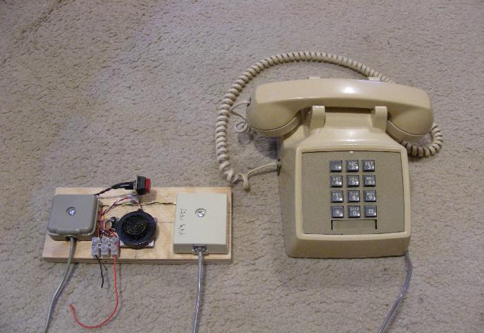
Telephone Intercom Powered Master Set
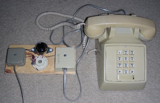
Telephone Intercom Remote Slave Set
This project involves the use of two Bell System compatible telephones to make a low-power intercom system. This is a no-frills minimalistic design that was put together using the Simpler Is Better (SIB) design philosophy. Both touch-tone and rotary-dial telephones can be used for this project.
To simplify the design, external ringers were used instead of the built-in telephone bells. The touch-tone keypads on the phones are active but are otherwise not used. The intercom is designed to work with standare four-wire telephone wiring, this allows it to be run on unused telephone wiring that is already installed in a house. The intercom can also be used to communicate between a house and an external building.
Both sides of the intercom consist of a telephone set and a small interface board. The Master side runs on 12VDC (nominal) power and the remote side does not require any power supply. Power can be provided by 12V batteries, a solar-charged 12V battery or a small DC-output wall-wart power supply that provides between 9V and 15V. If both phones are in the on-hook state, no power is consumed.
Each interface board has a ringer pushbutton and a Sonalert type of piezoelectric buzzer. When a pushbutton is pressed, the buzzer on the opposite interface board will beep.
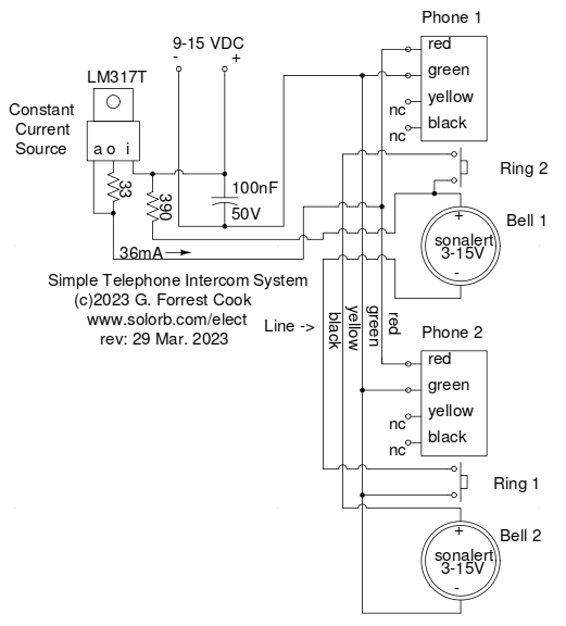
The heart of this system is the 36mA constant-current regulator circuit that consists of an LM317T voltage regulator and a 33 ohm 1/2W resistor. The regulator receives its power from the external DC power input. The two telephones are wired in parallel and will receive either 36mA when one phone is off-hook or 18mA when both phones are off-hook. If both phones are on-hook and neither ring button is pressed, the circuit will draw no power. Two phones will also work if they are connected in series with each other and a current source, but the parallel configuration has the advantage of running from a lower voltage power source.
The ringer circuits are powered from the DC power input through a 390 ohm 1/2W current-limit resistor, this resistor prevents excess current from flowing in the event of a short circuit in the wiring. In order to work with a 4-wire phone line, one ringer sonalert is switched on the negative side and the other is switched on the positive side.
The Ring 2 button on Phone 1 connects + voltage from the 390 ohm resistor to the yellow line wire which activates the Bell sonalert on Phone 2. This sonalert is grounded via the green line wire. The Ring 1 button on Phone 2 connects ground via the green line wire to the black line wire, which activates the Bell sonalert on Phone 1, the sonalert + side is connected to the + voltage source through the 390 ohm resistor.
Both the Master and Slave interface boards were built on scraps of 1/2" thick plywood. The four-wire phone line was connected to Western Electric type 42-A wiring blocks on each board, any terminal strip will work. The 42-A block was used since it is standard telephone equipment and just looks right in this application. The phones plug into RJ-11 female connector blocks using standard telephone wiring. A European-style connector block was used for connecting the 12VDC power to the Master interface board.
The ringer pushbuttons were screwed onto the interface boards using short wood screws. The sonalert buzzers were attached to the interface boards using hot-melt glue. The current-limiter circuit was attached to the Master interface board with a small wood screw. All of the wiring was done with scraps of solid copper telephone wiring and was routed between the two terminal blocks and the external components.
While the touch-tone pads on the phones are not used here, they still produce sound when pressed and can be fun to play with. Note that some telephones are polarity-sensitive, if the touch-tone pad does not produce any sound, try swapping the red and green wires on the RJ-11 wiring block
Apply 12VDC power to the master interface board. Pick up the handset on either side and press the ringer button to alert the person on the other side to pick up their handset. When the other handset is picked up, you can have a conversation. Hang up the handsets when the conversation is done. Note the relatively good-quality and full-duplex audio compared to modern cell phones and VOIP systems.
Back to FC's Telephone Circuits page.