(C) 2000-2004, G. Forrest Cook W0RIO (formerly WB0RIO)
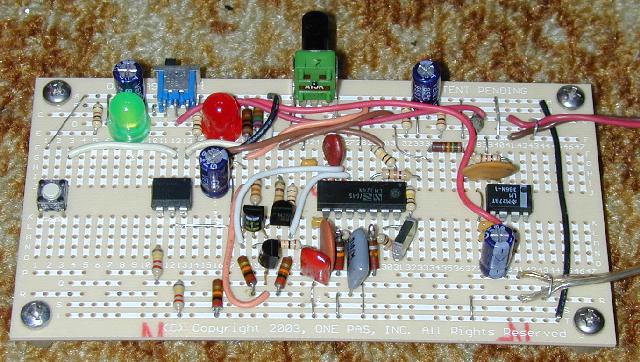
Rev 2c prototype on OnePas OP840B prototyping circuit board
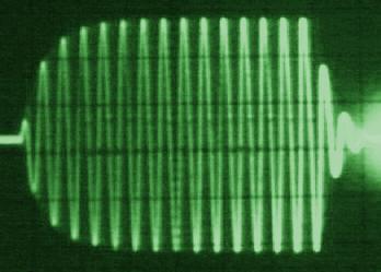
Waveform of one morse code "dit"
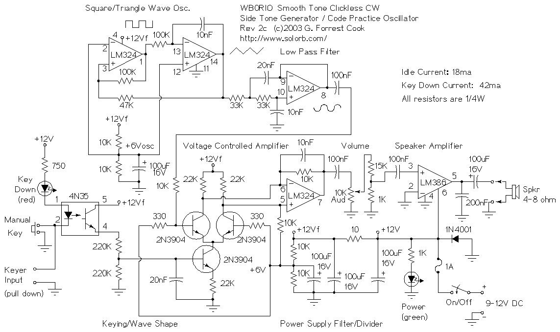
This circuit is about as good as it gets for generating morse code tones. It may be used as a code practice oscillator, a tone generator for a keyer, a sidetone oscillator for a CW transmitter or an audio Modulated CW (MCW) generator for an FM transmitter or repeater.
Feng shuei is the Chinese art of arranging objects in buildings, it is based on many practical ideas. One important concept of feng shuei is the rounding of sharp corners so that you don't scrape yourself when walking by. Think of this circuit as a form of electronic audio feng shuei ;-).
One may think this is a lot of circuitry just to make simple beep tones, but the real value of the circuit is that it sounds very smooth when compared to a clicky and harsh-toned square wave code oscillator. This circuit is easy on your ears, even with extended use.
There are other applications for a clickless beeper, one reader was interested in cranking the frequency into the ultrasonic range for use as a dog training device.
The tone quality sounds just like a well shaped CW signal from the airwaves, minus the background noise. Morse code is much easier to listen to when the waveform is a sine wave and the tone's envelope rises and falls slowly.
Careful readers may notice the lack of a pitch control, this is mainly to keep the circuit simple. The components in the circuit shown produce a 500 hz tone. Changing the pitch requires the use of different part values on both the oscillator and low pass filter sections.
For a different pitch, change the value of the capacitor between pins 13 and 14 of the LM324, and change the two 33K resistors on pins 14 and 9 of the LM324, both resistors should be the same value. An easy empirical way to find the filter resistor values is to wire a ganged dual 100K potentiometer in place of the two 33K resistors. Adjust the pot until a good sine wave is achieved, then measure the resistance on the potentiometer. Substitute the nearest standard value resistors into the circuit.
A three pole, multi-position switch can be used to select a number of different tones and filter settings. Each tone requires a specific oscillator capacitor and pair of equal-value filter resistors.
This is revision two of the circuit, changes include the addition of the LM386 audio amplifier IC for greater audio volume, and electrical isolation of the keying input via the 4N35 opto-isolator. The isolation makes the circuit more immune to damage from static electricity zaps on the key.
To further purify the sine wave tone, you can mount a speaker in a tube and cut the tube so that it resonates at around 500 hz with the speaker in place. The resonant tube will also increase the volume.
If the circuit is to be used as a transceiver sidetone generator, remove the LM386 IC and feed the signal from the volume pot into the transceiver's audio circuitry.
This circuit will work over a supply voltage range of 9V to 14V. It could be run from a 9V battery, although the 18mA idle current would produce a fairly short battery life. The green power LED could be eliminated or its series resistor could be increased to around 5K to reduce the overall current drain.
This circuit is essentially a minimal version of an analog music synthesizer that is hard-wired for the purpose of making morse code tones.
The oscillator section produces a fixed frequency triangle wave on LM324 pin 14, that is fed into a low pass filter to get a sine wave on LM324 pin 8. A triangle wave can be thought of as a series of sine waves with decreasing amplitudes as the frequency increases. The low pass filter removes the upper harmonics and passes just the fundamental sine wave frequency through.
Note that while the LM324 is common and inexpensive, it is known to produce cross-over distortion in some audio circuits. A better quad op-amp such as a TL074N could be substituted for lower distortion.
The sine wave is sent to a voltage controlled amplifier made from three 2N3904 transistors. The upper two 2N3904 transistors should be a matched-gain pair from the same manufacturing batch in order to minimize thumping sounds. The VCA is modulated with a keying waveform to produce the resulting smooth-keyed waveform. The keying waveform is generated by smoothing out the square wave keyed signal on the 4N32 emitter with the 220K/220K/20nF (.02uF) capacitor/resistor low pass filter on the base of the lower transistor. The two 220K resistors in series with the 4N35 output transistor act as a voltage divider, this causes the the keying envelope to swing between 0V and 6V, which is a good range for controlling the VCA.
Keying of the circuit is performed either by the manual key input, or via the keyer input, which can be used to connect the circut to a morse code keying chip. To use the keying input, an active low open collector driver should be used.
The audio signal comes out of LM324 pin 7, it connects to a 10K volume potentiometer and an attenuator made with two resistors. The attenuated audio is then fed to the LM386 audio amplifier.
The 200nF capacitor on the audio output prevents the LM386 from generating spurious RF oscillations, which it likes to do. I originally tried using the series R-C network that is normally shown on LM386 application notes, but the LM386 would still break into RF oscillations.
The circuit nodes marked +12Vf are all connected together, this is the filtered +12V line. The +12V line is filtered through a 10 ohm resistor and across a 100uF capacitor, those components remove audio noise that may be present on the +12V supply.
A careful observer will notice that there are two identical +6V divider chains, one for the oscillator and one for the VCA. The first build of the circuit started with a single divider, but the oscillator tone changed when the circuit was keyed. A resistive divider feeding a unity gain op-amp buffer could be used to supply a low impedance 6V supply to both stages, but that would require another IC and would also consume more current.
The Sidetone Generator was built on a prototyping circuit board using point-to-point soldered wiring. The wiring pattern on this board is the same as that found on many wireless prototype plug boards. This makes it possible to build a temporary circuit on the plug board and transfer it to a more permanent layout on the circuit board. It should be fairly easy to copy the basic circuit layout just by looking at the above photograph. Note that there are a few trace cuts and insulated jumpers on the bottom of the board. Also, a few extra holes were drilled in the board to hold the potentiometer mounting leads.
David McClafferty, VE1ADH, has provided the following ExpressPCB circuit board files:
Amateur radio station DF9TS (Gerd) has had success with this circuit. He recommends building a matching resonant pipe speaker, which will increase the loudness and further filter the tone of the sine wave.
Paul Christensen (W9AC) produced a modified version of this circuit: CW-Sidetone-Generator.pdf (65K) that features a tuneable oscillator frequency and reduced key up feedthrough. The feedthrough in my circuit is inaudible as long as the two upper VCA transistors have reasonably matched gains. Modern transistors from the same manufacturing batch are usually sufficiently matched to work with the original circuit.
Back to FC's Ham Radio Circuits page.