(C) G. Forrest Cook June 23, 2006
Power this project from sunlight with a CirKits solar power circuit board kit.
The purpose of a voltage regulator circuit is to take a variable input voltage and produce a steady output voltage. Two common regulator types are linear and switch-mode. Linear regulators are simple, but waste a lot of power in the process of regulating the voltage. Linear regulators can be thought of as self adjusting series resistors.
Switch-mode regulators such as this one are much more efficient than linear regulators. Switch-mode regulators convert DC input voltages to pulses of DC current. The DC current pulses are used to charge an inductor. When the DC pulse is turned off, the inductor discharges through a schottky diode into a storage capacitor. The width or frequency of the DC pulses is varied by a feedback circuit in order to produce a regulated output voltage.
This circuit is suitable for a variety of uses. If you have a solar powered 12 Volt lead-acid battery power source, the circuit can be used to efficiently power lower voltage devices. It can be used to provide power to devices that normally use a set of small batteries for power. Common voltages such as 1.5V, 3V, 4.5V, 6V, 7.5V, and 9V can be produced by this circuit. The circuit has been used to power small fans, portable radios, a miniature TV, and more.
Another application for this circuit is as a "linear current booster" (LCB). Common LCB uses include running motors and other devices directly from a solar panel with no battery. In the LCB mode of operation, it is possible to use the circuit to change a low current solar panel input to a higher current (but lower voltage) output.
When the circuit is used as an LCB, the current rating of the solar panel should be sufficient to power the load through the regulator. A 12V 1 amp rated solar panel (about 10 watts) would be a good match for this circuit, panels with lower current ratings can also be used, depending on the output current requirements. As an example, and ignoring inefficiency issues, if you want to power a 6V device that consumes 1 amp, then a 12V panel that puts out 500ma should produce enough power to run the 6V device when the sun is shining.
The LCB mode of operation is not recommended for equipment with computers, such as an iPod or a PDA. A brief shading of the solar panel will cause the output power to drop and the computer will crash. If you want to power such a system from solar power, use a rechargeable battery, a solar panel and suitable solar charge controller.
Power Requirements:
Input Voltage: 7-20V DC (7-40V with slight modifications)
Output Voltage: 1.2-11V DC (for 12V input)
Output Current: 1A max
Switching frequency: 52Khz
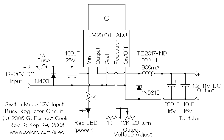
The 12V DC power is sent to the input of the circuit. The 1N4001 diode is used as a crowbar device, if reverse power is applied to the circuit, the diode causes a short circuit and the 1 amp fuse blows. The input voltage is stabilized with the 100uF capacitor, this is also used as a local power reservoir for the switching regulator. The red LED in series with the 1K resistor provide an indication that the circuit is powered.
The LM2575T-ADJ voltage regulator provides variable width DC pulses to the 330uH toroidal inductor. When the output pulse is on, the inductor stores energy, when the pulse turns off, the inductor discharges energy into the 330uF capacitor through the 1N5819 schottky diode. The 1K resister and 10K trimmer potentiometer form a voltage divider circuit, this is used as feedback by the LM2575T-ADJ IC for setting the output voltage. The 10uF tantalum capacitor is used to reduce the DC switching noise from the output circuit.
Connect the input of the circuit to a 12V power source, such as a solar-charged lead acid battery. Adjust the 10K trimmer potentiometer for the desired output voltage. Connect the load device to the output connections, and power up the load. For the best power efficiency, be sure to switch off the input power to the regulator circuit when the load circuit is not in use.
For use as a linear current booster, connect the circuit input to a 36 cell (18V, 12V nominal) solar panel. Put the solar panel in the sun and adjust the 10K trimmer potentiometer for the desired output voltage. Connect the lower voltage load device to the output connections and power up the load. In this mode of operation, there is no storage battery, so the load only works when the sun is shining on the solar panel. The regulator IC will accept input voltages up to 40V DC, this allows the circuit to be used with 36V (24V nominal) solar panels. If you use this circuit with input voltages above 22V, change the 100uF capacitor to a 50V part.
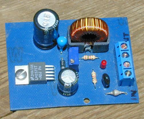
There are a few unusal parts in this circuit. The 330uH inductor was available from digikey.com as part number TE2017-ND, but may have been discontinued. Other inductors can be used, but they should be designed for use in switching power supplies. Jameco.com sells a J.W. Miller 2218-V coil (330uH, 3.3A) part #371434 that should work. The output filter capacitor section uses a 330uF electrolytic capacitor in parallel with a 10uF tantalum capacitor. It is possible to use other capacitor combinations, such as a 330uF "Low ESR" type electrolytic capacitor and a 100nF ceramic disk capacitor or a standard 330uF electrolytic capacitor in parallel with a 1nF disk capacitor and a 100nF mylar capacitor. The small value capacitors improve the high frequency rejection of the electrolytic device.
Back to FC's Solar Circuits page.