
(C) 2007, G. Forrest Cook
The SPC3 is a solar power center circuit board, it contains all of the power functions for a solar-charged 12 Volt DC system. The SPC3 contains a 9 amp photovoltaic charge controller circuit, a 10 amp low voltage load disconnect circuit and a pair of built-in white LEDs for illumination. The charge controller features a red/green LED for indicating charging and float conditions. The low voltage disconnect circuit has a load on-off switch and a battery low voltage indicator which lights up before the load shuts off during low voltage conditions. By using the SPC3 as the center of a solar powered device, long battery life is insured. The SPC3 can be used as the controller for a stand-alone solar lighting system, it is also suitable for making solar powered audio and radio devices.
The SPC3 was originally a kit sold under the CirKits brand, the kit has been discontinued. A few minor revisions to the original kit are shown in this article.
The SPC3 circuit was designed with the following goals:
A single-board smart solar power system with a self-contained LED lamp.
Simple analog circuitry that uses common parts for ease of repair.
Low-loss charging and minimal idle current for high efficiency.
Radio-quiet operation using low frequency charge controller switching.
Manual load switching with built-in low voltage disconnect circuitry.
Capable of handling resistive, inductive and capacitive loads.
Temperature compensation for optimal battery charging across a wide range
of operating temperatures.
Supported battery types: 12VDC lead acid, 0.5 to 200 Amp-hours
Maximum solar panel short-circuit current: 9 Amps
Maximum load current: 10 Amps.
Night time battery drain current: 150 micro-amps
See the full SPC3 specifications for more details.
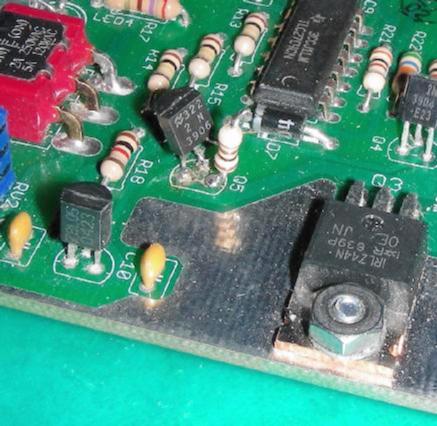
The charge controller is shown in the upper half of the schematic. When the PV panel's voltage rises above 12V, current flows through zener diode ZD1 causing transistor Q2 to turn on and send power to voltage regulator VR1. VR1 provides 5 Volt power to the rest of the charge controller circuitry. The charge controller power is supplied by the battery when the sun is shining on the PV panel. During the night, the Q2 circuit turns off and prevents the charge controller from draining battery power.
The upper half of IC1 is the heart of the charge controller. It acts as a comparator/oscillator circuit. When the battery voltage is well below the float voltage setting, IC1 turns on, this causes the LED to turn red and the 4N35 opto-coupler to turn on. The output of the 4N35 activates FET Q1, which connects the solar panel power to the battery through Schottky diode SD1.
When the float voltage is reached, the circuit oscillates just above and below the float setting and battery charging current is switched on and off. The oscillation frequency changes with the battery's state of charge and the available PV panel current. The maximum switching frequency of IC1 is limited due to the hysteresis provided by R11 and the low-pass characteristics of R6,RV1,R8 and C4.
The thermistor TM1 modifies the float voltage to a slightly higher value when the circuit experiences colder temperatures. This thermal compensation improves cold weather battery charging.
The lower half of IC1 always produces the opposite output from the upper half of IC1, this is used for driving the bipolar state indicator, LED1.
If the equalize terminals are shorted together, the preset float voltage setting will rise. This is useful for occasionally overcharging (equalizing) a battery.
Schottky diode SD1 prevents battery power from leaking back into the solar panel at night. Diode D1 is wired as a crowbar circuit, if the battery is connected in reverse the fuse will blow, saving the rest of the circuitry from destruction.
The smart switch and low voltage disconnect circuitry is shown in the lower half of the schematic. The circuit operates like a solid-state version of a latching relay. Unlike simple voltage controlled switch devices, when the LVD circuit shuts off, it stays off until it is manually turned back on with a flip of switch S1. This action prevents the load from oscillating off and on due to the rise in battery voltage after the load is disconnected.
When momentary switch S1 is turned on, transistor Q5 is turned on. This activates the comparator circuits formed by IC2d and IC2c. When the circuit is active and battery voltage is above the LVD setpoint, the IC2d comparator output goes low and transistor Q4 is switched off. This allows gate drive voltage to reach Q3, Q3 connects battery power to the load. Resistor R16 bleeds off the gate drive voltage from capacitor C8 when the circuit shuts off.
When momentary switch S1 is turned off, the Q3 gate drive voltage is shorted to ground, causing load power to be switched off.
IC2a and IC2b form a square wave oscillator that produces a frequency of approximately 350 Hz with a voltage swing from 0-12V. The output of the oscillator is fed to the D3,D4,D5 voltage multiplier circuit to produce the Q3 gate drive voltage, this is typically around 18.3V. Q3 requires a gate drive voltage above 12V since it is wired to switch the high side of the load.
Once the LVD circuit has been turned on, diode D7 feeds the load power back to the circuit to keep it active. Power to LED3 and LED4, the two white LEDs is routed through current limiting resistor R17.
Regulator VR2 provides a reference voltage for the oscillator circuit and for the battery voltage comparators IC2c and IC2d.
IC2c is the low battery voltage sensing comparator. When the battery reaches 0.6V above the shutoff point, the IC2c output goes high and turns on the yellow LED. Resistor R21 sets the difference between the low voltage indication and the power shutoff setpoint.
Diode D8 protects the circuit from reverse voltage spikes when driving an inductive load such as a relay or motor.
Connect the PV panel and battery to the circuit, put the PV in full sun. Turn the float voltage setting fully clockwise, the dual color LED should turn red. Connect a volt meter across the battery and monitor the battery voltage. The battery voltage should gradually rise while the sun shines.
Leave the circuit connected until the battery voltage has reached or exceeded the desired full-charged setting, this is typically around 13.8V at room temperature. Turn the float voltage setting counter-clockwise until the LED alternates red and green. Adjust the setting until the LED blinks and the battery voltage is where you want it to be at the full state. When the LED is alternating red/green, it is normal for the battery voltage to vary by about 10mV.
If a battery pack with a float voltage setting below 13V is used with the SPC3 (NiMH for example), zener diode ZD1 should be changed to a 1N4740 (10V) and resistor R6 should be changed to 250K.
Disconnect the battery from the SPC3 and connect a variable voltage power supply that can produce 10 to 15 Volts across the SPC3 battery connection. Observe the correct polarity. Set the variable supply to 11.6 Volts. Turn the LVD Setpoint pot fully counter-clockwise. Turn the power switch on. The White power LEDs should turn on. Turn the pot clockwise until the yellow low voltage LED just turns on. Monitor the supply voltage while you decrease it, at around 11V, the LVD should turn off the white LEDs. Repeat the adjustment if you wish to fine-tune the shutoff voltage.
Connect a 12V rechargeable battery, photovoltaic panel, and a load to the SPC3 circuit board.
As sun shines on the solar panel, the circuit will pass charging current to the battery. The dual color LED will turn red while solar charging is taking place. When the battery voltage rises to the full setpoint, the charging current will be periodically cut off and the LED will alternate red and green.
The load can be operated during daytime charging and at night.
The on/off switch controls the load like a normal power switch. If the battery voltage drops to 0.6V above the shutoff point, the yellow LED will turn on to warn of an impending shutdown. If the battery voltage drops further, the circuit will shut the load off, preventing deep discharge of the battery. This will greatly extend the life of the battery.
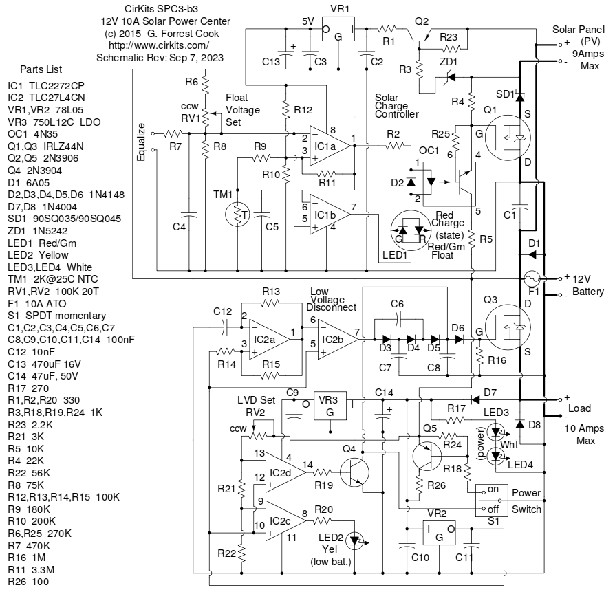
The SPC3-a and SPC3-b1 kit versions should have the following modification: R4 (47K) has been changed to 22K and R25 (270K) has been added across pins 4 and 6 of OC1, the 4N35 opto-coupler. This fixes a problem where the charge controller can lock on and the R/G LED stays green after the sun sets. The problem is more likely to occur if there is residual solder flux around OC1 on the circuit board. The photo below shows the placement of R25, the 270K resistor. For already assembled kits, it is easier to solder a 39K resistor in parallel across R4 (47K) instead of unsoldering and replacing R4. SPC3 kits sold after May 16, 2013 include the new value of R4.
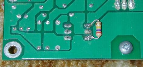
The SPC3-a and SPC3-b1 kit versions should also have the following modification: Transistor Q5 may permanently short on if voltage spikes are present on the battery line. The symptom of this problem is the on/off switch does not turn the load off. This problem can be fixed by replacing the defective 2N3906 and installing 100 ohm resistor R26 in series with the Q5 collector to limit the collector current. The photo below shows the modification, the Q5 collector was unsoldered from the PC board and R26 was placed in series with the collector lead and the PC board.
The standard SPC3 circuit only supports PV panels with a maximum output voltage of 20V. If you would like to use the SPC3 with a panel that has an open-circuit voltage from 20V to 26V, such as the amorphous type, you should perform the SPC3-b1 High Voltage PV panel modification. The above three revision are included in the SPC3-b3 schematic (above).
Some battery types such as Absorbed Gas Mat (AGM) lead acid may require a higher float voltage setting. The float range can be raised by increasing the value of R6 from 270K to 300K or 330K.
The standard SPC3 circuit requires that the load be turned on manually with a switch. The SPC3 Automatic Load Turn-on circuit can be added for automatic powering of the load when the battery voltage rises above a setpoint.
Back to FC's Solar Circuits page.