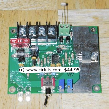
A kit with the circuit board and parts for this circuit is available from CirKits.com.
(C) 2007-2021, G. Forrest Cook
The DAS1 is a combination manual switch and automatic dark-activated switch. It is designed to control up to 10 amps of load at 12V DC. A pair of high-intensity white LEDs are included in the circuit for built-in lighting and as a power-on indicator. The circuit includes a low voltage disconnect circuit that prevents excessive battery discharge when running on battery-powered systems.
The DAS1 is ideal for solar powered lighting systems, it can also be used for line powered applications. External 12V lights consisting of white LEDs, incandescent lamps and/or fluorescent lamps can be controlled by the DAS1. The DAS1 features a common ground connection between the battery and the load which makes it useful for automotive and marine applications.
The design goals of this circuit were efficiency, simplicity, reliability and the use of field replaceable parts. The DAS1 circuit is designed to work in conjunction with the SCC3 Solar Charge Controller, which is also available in Kit form.
When using a solar-charged battery with the DAS1 circuit, the battery's amp-hour rating should be matched to the photovoltaic panel's charging capacity and the desired lamp load's discharging capacity.
With a minor modification, the DAS1 can become a Light Activated Switch, this allows the circuit to activate loads that you want to run while the sun is up.
Supply voltage: 12V (nominal).
Maximum lamp control current: 10A at 12V.
Day/Night battery current drain (off): < 10 microamps
Day battery current drain (auto): 5mA @ 12.8V
Night battery current drain (on or auto, load disconnected, LEDs on): 27mA @ 12.8V
See the full DAS1 kit specifications for more details.
Here are the DAS1 kit alignment instructions.
My FC's LED Circuits page has a number of 12V lamps that will work nicely with the DAS1.
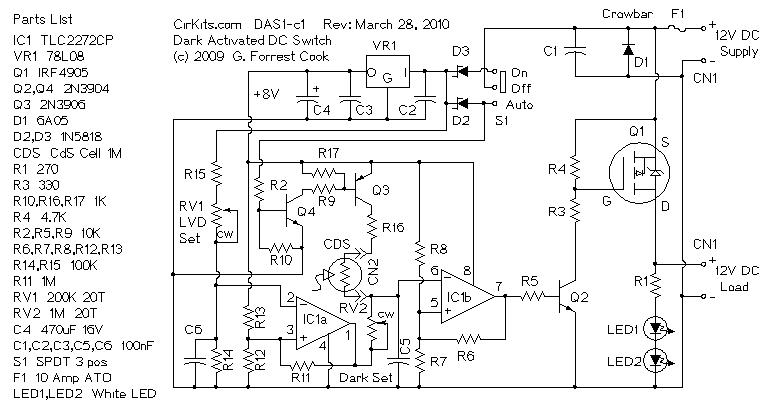
12VDC power is supplied to the DAS1 circuit via connector CN1. Diode D1 protects the circuit from reverse supply voltage, if the supply is reversed, D1 conducts heavily until fuse F1 blows. Power is routed to the control circuitry through switch S1 and schottky diodes D2 or D3. With the switch in the Auto position, power is sent to the CdS cell via the level changing circuitry consisting of transistors Q4 and Q3. When the switch is in the On position, Q4 and Q3 are forced off, simulating a dark condition on the CdS cell.
Regulator VR1 lowers the supply voltage to a constant 8V for powering the control circuitry. Op-Amp IC1a is wired as a voltage comparator circuit, it functions as the Low Voltage Disconnect. When the supply voltage is above the LVD setpoint, the sense line on IC1a pin 2 is above the reference voltage on IC1a pin 3 and the output of IC1a is low. When the supply voltage drops below the LVD setpoint, the output of IC1a goes high, disabling the light sensor circuit and shutting off power to the load. Resistor R11 provides hysteresis action on the LVD circuit, preventing oscillation when the supply voltage is near the LVD setpoint. Variable resistor RV1 adjusts the low voltage disconnect setpoint.
Op-amp IC1b is wired as another voltage comparator circuit, it measures the light level on pin 6. Bright light on the CdS cell cause the voltage on pin 6 to rise above the reference voltage on IC1b pin 5, this in turn causes the IC1b output on pin 7 to go low. Low light on the CdS sensor causes the voltage on IC1b pin 6 to go below the pin 5 reference voltage and the IC1b output will go high. Resistor R6 provides hysteresis to the light sensor circuit, preventing light flicker at dusk and dawn. Variable resistor RV2 adjusts the dark turn-on point.
The IC1b output signal is sent to transistor Q1, which pulls the gate of power MOSFET Q1 down (on) or up (off). Q1 controls the flow of current from the supply to the external load pins on CN1. The two white LEDs are connected across the external load pins through current limiting resistor R1.
Connect the battery to the DAS1 battery terminals. Connect the external lamps to the DAS1 load terminals. The light sensitive CDS cell can either be screwed directly to the two CDS screw terminals on the DAS1 circuit board, or remotely mounted. The CDS cell should be placed in a location that is not exposed to light from the onboard LEDs or any external lamps.
If the CDS cell is to be remotely mounted more than 5 feet from the DAS1 circuit board, two conductor shielded cable should be used. The remote CDS sensor should connect to the DAS1 via the two internal wires and the shield conductor should be connected to the DAS1 load minus screw (ground), the shield wire should be left floating on the CDS sensor end.
When the DAS1 switch is put in the ON position, the two onboard white LEDs and the external lamp(s) will light up. When the DAS1 switch is put in the AUTO position, the two onboard LEDs and the external lamp(s) will light up if the CDS sensor is in the dark.
The DAS1 can also be used as an automatic 10 amp low voltage disconnect (LVD) switch by simply placing the circuit in ON mode.
If the DAS1 is operated from battery power, the onboard and external lamps will turn off as soon as the battery voltage drops below the LVD setpoint. The low voltage disconnect function works for both ON and AUTO settings.
As mentioned above, the DAS1 logic can be modified so that it turns a load ON when the optical sensor is in the light and OFF when the light goes away. This can be used on solar powered systems which power a load when the solar panel is producing charging current. Examples of this use include a radio beacon that only operates during the day and a solar-powered water fountain.
The modification for turning the DAS1 into a light activated switch is simple, cut the circuit board trace between R16 and CN2, the CDS cell connection. Cut the trace between the CCW side of RV2 and IC1a pin 1/R11. Install two jumpers to cross-wire this part of the circuit. One jumper goes between the cut end of R16 and the CCW side of RV2. The other jumper goes between IC1a pin 1/R11 and the cut end of CN2. RV2 should be adjusted so that the load turns on at the appropriate light level.
A kit version of the dark activated switch circuit is available from CirKits.com, buying the kit will save you time locating parts and wiring the circuit.
Back to FC's Solar Circuits page.