Power this project from sunlight with a CirKits solar power circuit board kit.
Other LED lamp circuits can be seen at FC's Solar Circuits.
(C) 2006 G. Forrest Cook
DC powered LED lighting circuits can vary from trivial single LEDs with series resistors and LEDs with simple analog current regulators to more complicated switching power supply circuits such as this project. There is a tradeoff between simplicity and circuit capabilities. This more complex circuit adds features such as regulated light level across a wide range of input voltages and automatic circuit shutoff on low input voltage.
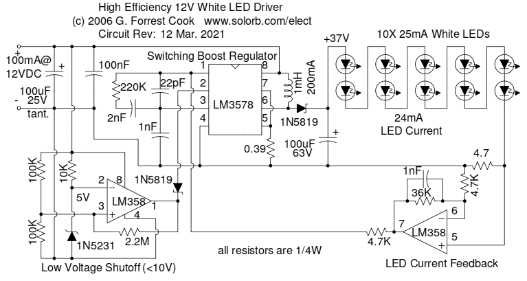
By using a high frequency switching regulator, the power loss associated with the current dropping resistors found in simpler circuits is reduced. This offsets the power consumed by the circuit's active parts. This circuit can power 10 white LEDs at 24mA of current with only 100mA of input supply current when running on 12V DC. The LED intensity is fully regulated across the entire operating voltage range.
This circuit was inspired by F. Garcia's IR LED video illumination circuit, published in the July 2001 edition of Nuts and Volts magazine. I modified the LED type and the feedback circuit, and added the important low voltage shutdown feature which prevents the LM3578 regulator from self-destructing when the supply voltage drops below 10V.
Power Requirements:
Operating Voltage: 10-18V DC
Operating Current: 100mA @ 12V DC (10 LEDs)
Current at low voltage shutoff point: 5mA
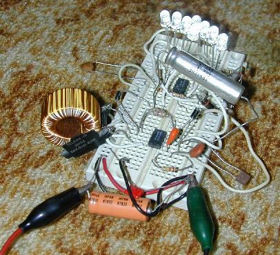
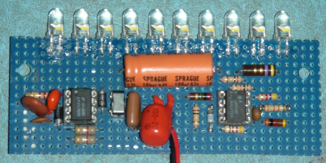
This circuit drives a string of ten white LEDs. The LEDs are wired in series and are powered by a current-regulated step-up switching power supply circuit.
The LM3578 switching regulator and its associated inductor, 1N5819 schottky diode, and 100uF 63V capacitor step the 12V power supply up to a higher DC voltage, approximately 3.7 times the number of LEDs. The 4.7 ohm resistor on the cathode end of the LED string develops a voltage that is proportional to the current through the LEDs. This voltage is amplified by half of the LM358 op-amp which sends a negative feedback signal through a 4.7K resistor back to the LM3578. The 36K op-amp feedback resistor sets the LED series current to approximately 24mA. Not all general purpose op-amps will work in this circuit, the LM358 is used because it can operate from a single-rail power supply with both input pins near 0V.
The other half of the LM358 (pins 1,2,3) is wired as a 10V voltage comparator. The 1N5231 zener diode and 10K series resistor produces a steady 5V on pin 2 of the LM358. The two 100K resistors on pin 3 of the LM358 divide the power supply voltage in half. If the supply voltage drops below 10V the output of the LM358 goes low and pulls pin 2 of the LM3578 down through a 1N5819 schottky diode, causing the LM3578 to shut down. A schottky diode, with it's lower forward voltage drop, is required here in order for the LM3578 pin 2 voltage to go low enough to disable the circuit. Without the low voltage shutdown circuit, the LM3578 current will increase as the supply voltage decreases until the IC self-destructs.
The 2.2M resistor across the LM358 produces a hysteresis effect for the low voltage shutoff. The circuit turns off about .25V below where it turns back on, this prevents oscillation around the shutoff threshold. When operated below the low voltage shutoff point, the circuit will consume about 5mA of current.
An interesting characteristic of this circuit is that it acts as a negative resistance at the power supply terminals. As the supply voltage is increased, the current will drop. The total power consumption stays nearly even across changing input voltage conditions. By comparison, a linear LED current regulator gets less efficient as the supply voltage rises above the point of regulation.
Connect the circuit to a 12V DC power supply such as a solar-charged lead acid battery. The light level will remain constant until the battery voltage drops below 10V, then the light will shut off. The circuit consumes a minimal amount of power.
It is possible to vary the number of white LEDs in this circuit from 8 to 12, as the LED count goes up, so does the regulator's output voltage and input current. The maximum numer of white LEDs that the LM3578 IC can drive is twelve. If you are driving lower voltage LEDs such as 1.4V IR, red or amber parts, the series string can have up to 30 LEDs.
1X LM3578AN switch-mode voltage regulator IC
1X LM358P dual op-amp
1X 1N5231 5V zener diode
2X 1N5819 schottky diodes
10X high intensity 25mA white LEDs
1X 100uF 25V electrolytic capacitor
1X 100uF 63V electrolytic capacitor, tantalum type recommended
1X 100nF 50V ceramic or MLCC capacitors
1X 2nF 50V ceramic or MLCC capacitor
2X 1nF 50V ceramic or MLCC capacitors
1X 22pF ceramic disc capacitor
1X 0.39 ohm 1/4 W resistor (Substitute: 2X 0.82 ohm 1/4W resistors in parallel)
1X 4.7 ohm 1/4W resistor
2X 4.7K 1/4W resistors
1X 10K 1/4W resistor
1X 36K 1/4W resistor
2X 100K 1/4W resistors
1X 220K 1/4W resistor
1X 2.2M 1/4W resistor
1X 1mH 200mA switching power supply inductor
    Inductors that are known to work:
      Mouser part 851-CDRH74NP-102MC (Sumida SMD)
      Digi-Key part TKS3504CT-ND (Toko 875FU-102M=P3)
Back to FC's LED Circuits page.