
(C) 2008, G. Forrest Cook
Alternative energy projects often require the movement of air or water from a warm place to a cool place for heating, or vice-versa for cooling. A differential temperature controller can be used to automate this process.
This device uses two electronic temperature sensors and some circuitry to detect the difference in temperature between the sensors. When the hot side sensor's temperature rises above the cold side sensor's temperature, the circuit applies power to a circulating device such as a fan or a pump.
The circulating device stays on until the two temperatures are equalized. This device can be used to improve the performance of the Self Powered Solar Box Furnace project, it has also been used to circulate hot water from a solar water collector through a storage tank.
Supply voltage: 12V (nominal).
Maximum load current: 10A at 12V.
Sensor temperature limits: -40c to +100c
Controls: Off-Auto-On switch
Indicators: High and Low LEDs
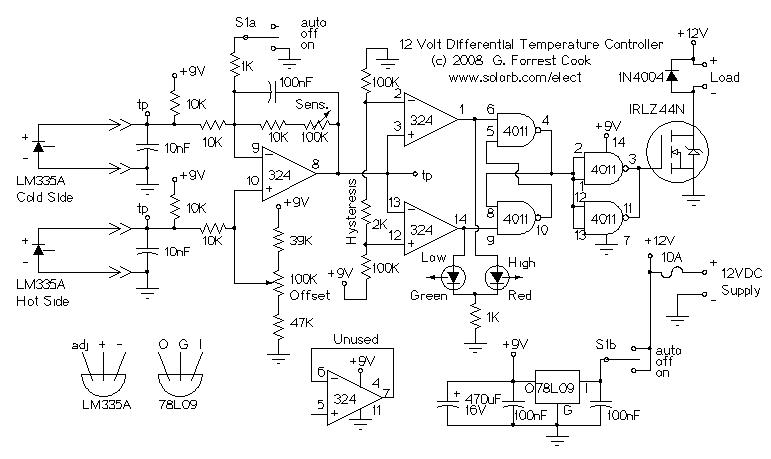
Power to the circuit is switched via half of the On/Off/Auto three way switch (DPDT center-off) and fed to the 78L09 9 volt voltage regulator. The 9 volt regulator powers the LM324 quad op-amp and the 4011 quad NAND gate.
Each of the two LM335A sensors produce a voltage that is proportional to the temperature (in Kelvin). The test points (tp) show the temperature of each sensor. The LM324 amp on the left is wired as a differential amplifier, the output on pin 8 is based on the difference between the two temperatures. The Sensitivity control adjusts the gain of the differential amplifier and the Offset control adjusts the offset between the two temperature sensors. The second half of the On/Off/Auto switch is used to unbalance the differential amplifier when in the On mode, forcing the rest of the circuit to stay in the on mode.
The right two LM324 amp sections are wired as a window comparator. The window comparator outputs feed to the left two sections of the 4011 NAND gate IC, which forms an R-S flip-flop. The window comparator and flip-flop function together to provide a single output that has a hysteresis (dead band) between on and off. If the circuit is on, it tends to stay on and if it is off, it tends to stay off. Note that the sensitivity adjustment affects the effective width of the dead band.
The output of the flip-flop drives the right two 4011 NAND gates, these are wired in parallel and drive the IRLZ44N logic-level input MOSFET. The MOSFET switches the negative side of the load on and off. The 1N4004 diode is used to supress inductive voltage spikes from the pump or fan motor.
When adjusting the circuit, observe both of the LEDs and monitor the voltage on the temperature difference test point (LM324 pin 8). The circuit flip-flops when the test point is above and below 4.5V.
Adjust the sensitivity control to the middle of its range. With both temperature sensors at the same temperature, adjust the offset control until both LEDs come on. Put the temperature sensors on the hot and cold sides of the controlled heating or cooling system and observe the operation. The offset control should then be adjusted so that the circuit doesn't come on until the warm side is significantly warmer than the cold side.
There is an inverse relationship between the circuit's hysteresis (dead band) and the sensitivity control. As you increase the sensitivity by raising the sensitivity control's resistance, the effect of the circuit's hysteresis will shrink. Adjust the sensitivity control for the desired amount of hysteresis.
Connect a 12VDC supply to the power terminals and a fan or water pump to the load terminals. Note that if the fan or pump's negative lead is grounded to its case, the case should be electrically isolated from ground so that the motor does not turn on.
In a heat pumping application, the cold side sensor should be thermally connected to the cold side of the object being heated and the hot side sensor should be thermally connected to the hot side of the heat source.
If the three way switch is on, the fan or pump will always stay on. If the three way switch is off, the circuit will be disabled and the fan or pump will always stay off. If the three ways switch is in the auto position, the fan or pump will go on when the hot side is warmer than the cold side and it will go off when the temperatures equalize.
The Red/Green LED will be Red when the fan or pump is running, green when the fan or pump is stopped, or both Red and Green during the transitional hysteresis state. Another way of saying this is that when the system is warming up, the LED sequence will be Green, Both, Red and when the system is cooling the LED sequence will be Red, Both, Green.
This schematic from the Free Info Society shows a simpler differential temperature controller circuit that runs directly from a PV panel (no battery). The circuit's ability to deal with large motor startup surge currents could be improved if one were to install a large capacitor, say 10,000uF at 35V, across the PV panel's output.
Back to FC's Solar Circuits page.