(C) 1999, G. Forrest Cook
This project can be used with a CirKits solar circuit kit.
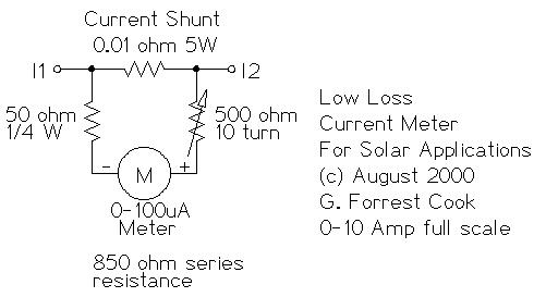
This circuit is used to measure the current from a solar panel. It has very low power loss for currents in the 0-10A range. It also works as a general purpose DC current meter. The circuit can be used on either the positive or negative side of a DC circuit.
Measured Current: 0-10 Amps DC, can be increased by changing the resistors.
Circuit Voltage: Will work with DC circuits at any practical voltage.
Accuracy: approximately 2% with a high quality meter movement.
The current to be measured flows through the 0.01 ohm resistor, this causes a small voltage drop across the resistor. 10 amps of current will produce a 100mV voltage across the resistor. The 100 microamp meter is wired in series with a 50 ohm fixed resistor and a 500 ohm variable calibration resistor so that it can measure the voltage drop.
The 500 ohm variable resistor is used to adjust the meter's full scale reading. The 50 ohm resistor limits the maximum current through the meter. The series resistance of the meter, the 500 ohm (or less) variable resistor and 50 ohm resistor should total 1000 ohms. Different meters may require a different variable resistor to achieve the 1000 ohm value.
Build the meter into a metal box with the meter and two connectors mounted on the outside of the box. Be sure to use connectors and wiring that are large enough to handle the full amperage from your PV array.
Put the meter circuit in series with a known current meter such as a digital VOM meter set to measure current. Run a known current through both meters. Adjust the 500 ohm resistor until both meters read the same current. A good way to get a known current is to put a 12V lead acid battery in series with a 2 ohm 100 watt current limiting resistor. This will produce approximately 6 Amps of current. Put the two meters in series with this loop and adjust for the same reading. Beware, the resistor will get fairly hot in a short time.
A PV panel is naturally current-limited and would also work well for alignment of this meter. Just wire the panel and two meters in a series loop and adjust the calibration potentiometer for the same reading.
Connect this circuit in series with a nominal 12V or 24V solar panel array. The meter can go in either the positive or negative side of the solar panel circuit. Negative side wiring can be safer from short circuit hazards. The current flowing through the solar panel to the load will be shown on the meter.
Note that the wiring in a PV system is slightly resistive and will have a measurable voltage drop. You can take advantage of that by using the system's wiring in place of the 0.01 ohm resistor. Just connect a small signal-wire to two places on either the positive or negative side of your PV system's feed wiring and send that to the meter and its two series resistors. Typical connection points would be at the PV panel's negative terminal on one side and where the PV's negative line connects to the charge controller on the other side.
The voltage drop across the PV wiring will vary with the wire gauge, the wire length and the maximum PV current. It may be necessary to adjust the value of the two series resistances and possibly the meter rating depending on the current to be measured.
1x 100 microamp DC meter
1x 0.01 ohm 5 W resistor
1x 50 ohm 1/4 W resistor
1x 500 ohm 10 turn variable resistor
2x banana plugs or a 2 pin screw type terminal block.
1x metal box
Newark Electronics
eBay for new and surplus meters
Back to FC's Solar Circuits page.