(C) 2002, G. Forrest Cook
This project can be used with a CirKits solar circuit kit.
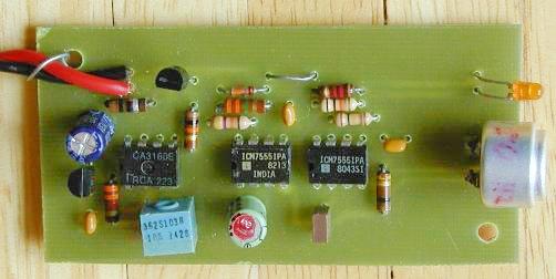
Photo of the assembled circuit
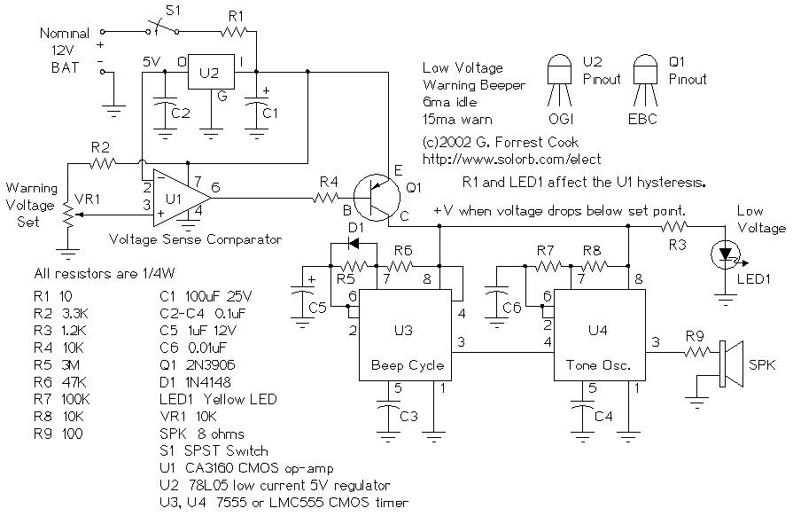
Schematic
This circuit provides an audible and visual low voltage warning for 12V battery powered devices. When the battery voltage is above the set point (typically 11V), the circuit is idle. If the battery voltage should fall below the set point, the LED will light and the speaker will emit a periodic beeping sound to warn of the impending loss of power. The circuit was designed for monitoring solar systems, but it could also be useful for automotive and other 12V applications. This design has been updated and is now part of the 12 Volt Battery Voltage Monitor (BVM1) project, kits are available from CirKits.com.
Nominal operating voltage: 12V
Idle current: 6ma
Low Voltage Warning current: 15ma
U2 provides a 5V regulated voltage reference. U1 is wired as a comparator, it compares the fixed 5V regulated voltage to the voltage on the wiper of VR1, that is proportional to the 12V supply. When the supply drops below the set point, the output of U1 goes low, turning on Q1 and powering the beeper and the LED.
The beeper consists of U4, a tone generator, and U3, a low duty cycle pulse generator. The tone can be changed by adjusting R7, the beep rate can be changed by adjusting R5. A small amount of hysteresis is provided by R1 and the current through LED1 and the beeper, this separates the on and off points for the circuit.
The circuit board was made by printing the pattern (see below) onto Press-n-peel blue circuit board transfer film with a laser printer. Etch the board, drill the holes, and assemble the parts on the board as per the board photo. Be sure to correctly orient the diode, electrolytic capacitors, ICs, and transistor. The CA3160 op-amp may be difficult to find, other low power CMOS op-amps may be substituted. A standard 741 op-amp would also work, but the idle current will be higher. The speaker shown was removed from an old computer motherboard, most of the larger electronics supply companies sell a variety of miniature speakers that will work for this circuit.
It is not shown in the schematic, but an inline fuse rated at 1 amp should be placed in series with the +12V input wire to prevent fire in the case of a short circuit. The circuit board should be mounted inside of a small plastic or metal project box, holes can be drilled in the box to accomodate the LED, on/off switch, speaker and power wires.
Connect the circuit to an adjustable DC voltage source. Set the voltage source to 11V or wherever you would like the circuit to turn on. Turn on switch S1. Adjust VR1 until the point where LED1 just comes on and the beeping starts.
Connect the circuit to the 12V source that you wish to monitor. Turn S1 on, if the battery voltage is above the set point, nothing should happen.
As the battery voltage drops below the set point, the LED will light and a periodic beeping will come from the speaker. If the beeping becomes annoying, turn off S1. Be sure to charge the battery soon, excessive discharging will shorten the life of most rechargeable batteries.
Printed Circuit Image (PostScript File)
Component Placement Silkscreen (PostScript File)
Jameco 1-800-831-4242 http://www.jameco.com/
Digi-Key 1-800-DIGIKEY http://www.digikey.com/
Back to FC's Solar Circuits page.