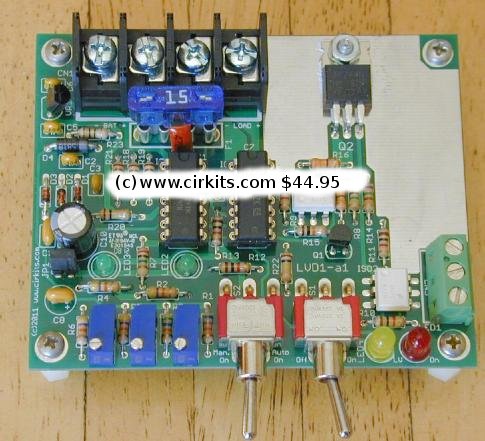
A kit with the circuit board parts for this circuit is available from CirKits.com.
(C) 2011-2021, G. Forrest Cook
This circuit provides a low voltage disconnect (LVD) function for battery operated 12 Volt DC power systems. It is ideal for use with solar powered battery systems. The LVD1 is designed to protect a battery from excessive discharge through a load. Rechargeable batteries will have a much longer life if they are never allowed to discharge below the manufacturer's recommended minimum voltage.
The LVD1 circuit supports common-ground loads by switching the high side of the load circuit. It uses a power MOSFET switch which is more efficient and reliable than a mechanical relay. The circuit is protected against reverse battery connection. The LVD1 circuit will work in conjunction with the SCC3 solar charge controller, both kits are available from CirKits.com.
The LVD1 features both Automatic and Manual modes of operation. The controls include an On-Off power switch and an On-Off-(On) switch for selecting the Auto-on and (Manual-on) modes of operation. An isolated low voltage detect signal is provided by the circuit, this can be monitored by a computer other device for a controlled shutdown prior to the disconnection of power.
Three trimmer potentiometer adjustments allow setting the On Voltage, Off Voltage and Low Voltage Warning point. Indicators include a Load On LED, a Low Voltage warning LED and two calibration LEDs.
In Auto-On mode, the On-Off-(On) switch is placed in the On position and load power is activated as long as the battery voltage is above the adjustable On Voltage reference point. When the battery drops below the adjustable Off Voltage reference point, the load power is disconnected. When the battery voltage rises above the On Voltage reference point, load power is once again activated.
In Manual-On mode, the On-Off-(On) switch is moved to the momentary (On) position to apply power to the load. The load power stays connected as long as the battery voltage is above the adjustable On Voltage reference point. When the battery drops below the adjustable Off Voltage reference point, the load power is disconnected and stays off until the switch is pressed again.
With a few minor modifications the LVD1 can be turned into a Low Voltage Connect circuit. This allows it to be used for controlling backup battery chargers.
Battery System Voltage: 12V (nominal)
Battery Voltage Range: 9V to 16V
Absolute Maximum Operating Voltage: 18V
Maximum Load Current: 15 Amps
Full Specifications for the LVD1 kit.
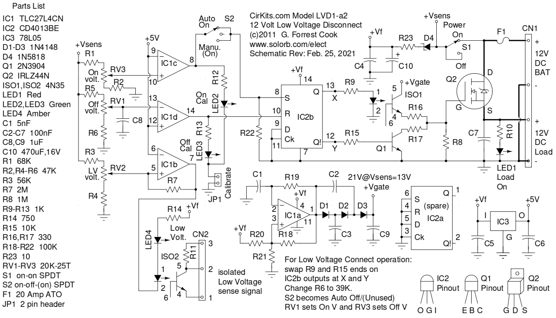
Power to the LVD1 circuitry comes from the battery connection on connector CN1 through protective fuse F1. Diode D4 protects the circuitry from reverse voltage and the lowpass filter formed by R23, C10, C4 and C5 remove electrical noise from the power line. The filtered voltage is called +Vf in the schematic, it is used for powering IC1, IC2 and VR1. Regulator VR1 provides a +5V reference voltage for use by the comparator circuits.
Op-amp IC1a is configured as an 800 Hz square wave oscillator. The oscillator drives a voltage doubler which consists of D1, D2, D3 and C2, C3, C9. The voltage doubler produces the +Vgate signal for driving the gate of the high-side power MOSFET current switch Q2. The +Vgate signal stays between 5-7 volts higher than the battery voltage, assuring that logic-level MOSFET Q2 always turns on fully. Note that this circuit will only work with CMOS rail-to-rail op-amps and logic-level MOSFETs.
IC1b, IC1c and IC1d are all wired as voltage comparators, they produce low or high outputs according to the three settable voltage sense levels. IC1c goes high when the battery voltage is above the On Voltage setting. IC1d goes high when the battery voltage is below the Off Voltage setting. IC1b goes low when the battery voltage is below the Low Voltage setting. LED2 and LED3 are connected to the output of IC1c and IC1d and are activated by connecting jumper JP1 during calibration. Resistor R7 provides hysteresis to the IC1b circuit, this prevents chatter in the LV signal.
If IC1c detects the On Voltage and the Mode switch S2 is set to Auto On, the set line of flip-flop IC2b is activated and the IC2b Q output goes high and the Q! output goes low. Load power is turned on. If IC1d detects the Off Voltage, the reset line of flip-flop IC2b is activated and the IC2b Q output goes low and the Q! output goes high. Load power is turned off. If S2 is set to Off, the LVD1 can be turned on by pressing the switch to the momentary Manual On side. The manual on function only works if the battery voltage is above the On Voltage setting.
When IC1b detects a Low Voltage condition, its output goes low and both LED4b and opto-isolator ISO2 are turned on. Resistor R7 provides hysteresis for the Low Voltage signal to prevent on/off chatter. Adjustable hysteresis is provided for the load on/off control by the proper setting of RV1 and RV3.
The two outputs of flip-flop IC2b drive transistor Q1 and opto-isolator ISO1 to switch the gate of Q2 between ground (off) and +Vgate (on). This allows MOSFET transistor Q2 to switch load power on and off. LED1 is wired across the load and lights when load power is present.
A kit that includes a circuit board and parts is available from CirKits.com. The circuitry can be built in "dead bug style" on a blank piece of copper-clad printed circuit board or wired point-to-point on a perforated board using IC sockets. The high current wiring (shown in heavy lines on the schematic) should be routed with appropriately thick wiring. Transistor Q1 should be mounted on an electrically isolated aluminum heat sink. If you will be running the circuit at the full 15 Amp capacity, be sure to use a large enough heat sink on Q1 so that the device stays cool when under load.
To align the circuit, first decide which off voltage, on voltage and low voltage detector settings you wish to use. Remember that a battery's voltage will tend to rise after a load is disconnected, so the on and off settings will need to be a few volts apart or the load may oscillate on and off when the battery is depleted. A good test is to connect the load directly to the battery and run the battery down to a suitable shutoff point (typically 10-11V for a lead-acid battery). Disconnect the load and see where the battery's voltage rises to, the On point should be set higher than that voltage.
Once you have decided which on and off voltages you wish to use, connect an adjustable DC power supply to the battery terminals and install the calibrate jumper to activate the LEDs. The power supply voltage should be adjustable between 0V and 15V. Caution: never exceed 18V input or the ICs will be damaged. Connect a digital voltmeter across the power supply terminals, or use the supply's voltmeter if it has one. Set the mode switch to Auto On and turn the power switch On.
Adjust the On Voltage trimmer RV3 so that LED2 turns on and off when the power supply is adjusted above and below the desired On Voltage. Set the Off Voltage trimmer RV1 so that LED3 turns on and off when the power supply is adjusted above and below the desired Off Voltage. Set the Low Voltage adjustment trimmer RV2 so that LED4 comes on at the appropriate low voltage setting. This last setting should be done by adjusting the power supply from high to low, the hysteresis in the Low Voltage circuit will separate the off and on points by about 0.5V. The Low Voltage setting should typically be a few tenths of a volt above the Off Voltage setting.
At this point, the circuit should be adjusted correctly. Verify the correct operation by moving the power supply voltage up and down and observing LED1, the load LED, turning on and off at the desired voltages and LED4, the Low Voltage LED turning on just before LED1 goes off. When you are satisfied with the circuit's alignment, remove jumper JP1 so that the circuit uses less power.
Connect the battery and load to the LVD1 circuit with 14 gauge or heavier stranded copper wire, crimp-on spade lugs are recommended. Turn the power switch On. Set the mode switch to either Auto-On or Manual-On. The load will receive power, assuming the battery voltage is above the On Voltage setting. As the battery drains, its voltage will drop and the Low Voltage LED will light up. When the battery voltage drops to the Off voltage setting, the load power will be shut off. The Low Voltage LED will remain on until the battery voltage rises above the Low Voltage setpoint.
As with all high-current devices, be sure to insulate and physically secure all wiring to prevent shorts and fires. Always include a circuit breaker or fuse and switch between the battery's + terminal and all other devices connected to the battery.
If you plan on using the isolated Low Voltage detect signal to reset a computer, connect pin 1 of CN2 to the computer's ground line and connect pin 2 of CN2 to the computer's active-low reset line. For monitoring the low voltage signal with a computer's digital input line, connect pin 1 of CN2 to ground and pin 3 of CN2 to the computer's V+, the signal on pin2 of CN2 will go low when the Low Voltage condition is detected. Your software can monitor this input and perform a controlled shutdown when the signal goes low.
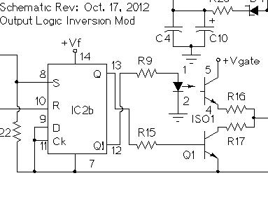
The LVD1 control logic can be inverted so that it can activate an outboard battery charger or generator starter when the battery is low. The circuit below shows the output logic inversion modification to the LVD1, it involves swapping the two outputs of flip-flop IC2b. The LVD1 load connection can drive an AC-output solid state relay to switch on power to an AC-operated charger. The LVD1 load connection can also drive a DC-output solid state relay or a 12VDC mechanical relay for controlling a generator starter circuit.
When using an AC charger, the charger's output should be tested to see if its DC output connection consumes reverse current from the battery when the charger is powered off. If this occurs, a suitably rated Schottky diode should be put between the AC charger's output terminals and the battery to prevent the reverse current from discharging the battery.
| 
|
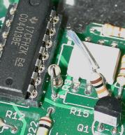
The above schematic and photo show the output inversion modification which was performed on an LVD1 kit's circuit board. The IC2 side of R9 (1K) and R15 (10K) are interchanged to invert the output logic. A piece of insulated tubing has been used on the long lead of R15 to insure against short circuits.
The functions of RV1 and RV3 will be swapped, RV1 becomes the "on voltage" adjustment and RV3 becomes the "off voltage" adjustment. Resistor R6 should be changed from 47K to 39K, this will raise the voltage range of RV1 to 11-14V so that the remote charger can be shut off at a higher battery voltage. Switch S2 will also have a new behavior, the "Auto Off" position is now "Auto On" and "Manual On" is unused, switch S2 should be left in the "Auto On" position.
The LVD1 can power a simple microprocessor such as an Arduino with no modifications. Higher power single board computers (SBC) such as the Raspberry Pi or BeagleBone run advanced operating systems and the computer should be shut down prior to removing power.
When the LVD1 is used to control power to an SBC, the computer is normally configured to shut itself down when the LVD1 Low Voltage signal turns on. If the computer halts, it will stop consuming significant power, the battery voltage will stop dropping and the LVD1 may not reach the OFF state and the load power output will stay on. If the battery voltage rises again from the charging source, the computer will not automatically restart since the power was never shut off.
This timed shutoff circuit can be used with the LVD1 to allow the computer to be gracefully shut down, then the LVD1 load power is automatically turned off a number of seconds after the computer halts. This example shows the timed shutoff circuit interfaced to the LVD1 and a Raspberry Pi single board computer. Note that the Pi should receive its 5V power source from a DC-DC converter that is run from the +12V Load terminals on the LVD1.
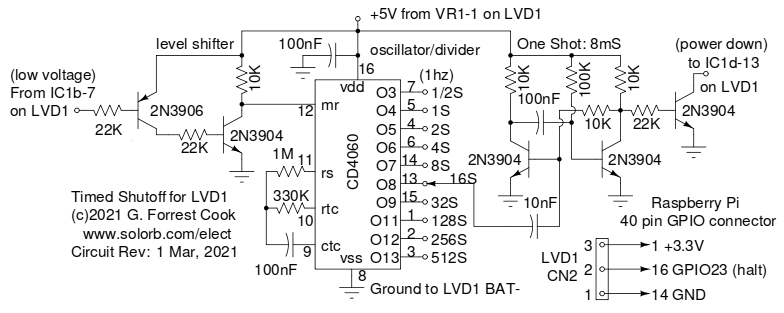
The timed shutoff circuit monitors the low voltage detect circuit on the LVD1, this signal is set to trigger at a voltage just above where the LVD1 shuts off power to the load. When the low voltage is detected, the level shifter circuit takes the 4060 oscillator/divider circuit out of reset and the chip starts counting up from zero. The various outputs from the 4060 rise on a specified number of seconds. When the selected output rises, this triggers the one-shot circuit and an 8mS pulse is sent to the final pull-down transistor. The pull-down transistor causes the LVD1 off-voltage comparator to trigger and shut the load off.
The computer should monitor the low voltage signal coming from CN2 on the LVD1. When the low voltage signal is detected, the computer should shut itself down. The 4060 output that is selected should have a longer time duration than the computer shut down time. On a Raspberry Pi model 2b, shutdown takes about 10 seconds, so the 16 second timeout value was selected on the 4060 IC. A good starting point for the LVD1 setpoint voltages are: On Voltage: 13.0, LV Voltage: 11.5V, Off Voltage: 11.0V.
This GPIO shutdown script for Raspberry Pi allows the Pi to be shutdown by a signal on a GPIO input pin. The GPIO input, ground and +3.3V power line should be connected to connector CN2 on the the LVD1.
Back to FC's Solar Circuits page.