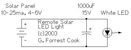
(C) 2003 G. Forrest Cook
This circuit was created as an attempt to make the simplest possible solar-powered project. The solar panel converts sunlight into a small electric current and the current is used to power a single white LED. This project would make an excellent science fair project and is a good introduction to solar-powered electronic circuits.
The circuit has some practical uses such as shedding some light into a dark part of your house such as a basement closet. It can also be used as a remote daylight indicator or even a detector that senses car headlights.
Most electronic hobbyists eventually end up with a few spare PV chips or small PV panels and LEDs are literally a dime a dozen, this device can put some of those unused parts to work. This circuit has been working reliably for 18 years, the electrolytic capacitor will probably be the first component to wear out.
Operating Voltage: 3.7V DC
Solar Current: 25mA max
LED Lamp Operating Current: 10-25mA
The remote solar powered LED light takes advantage of the current-limited nature of solar photovoltaic cells. If light shines on the solar array, current will flow through the circuit. For a typical size of solar cell, there is a maximum current that can be produced. The maximum solar cell current is simply matched to a value of current that the LED can safely handle. If there is enough light to raise the solar panel's voltage above around 3.7V, the white LED will light up. The LED regulates the maximum voltage across the circuit to around 3.7V. The capacitor optional but is recommended since it will keep the LED from flickering if the panel is briefly blocked, such as when a bird flies by.
If the solar panel that you use produces more than 25ma through your LED, it may be necessary to insert a series resistor between the LED and the solar panel. The resistor acts as a current limitor and prevents the LED from burning out. A 47 ohm 1/4 watt resistor is probably about right for the job, the exact value may need to be optimized to your particular PV panel. Insert a milliamp meter in series with the LED to measure the current. If you use a 20mA LED, be sure to limit the current to that value.
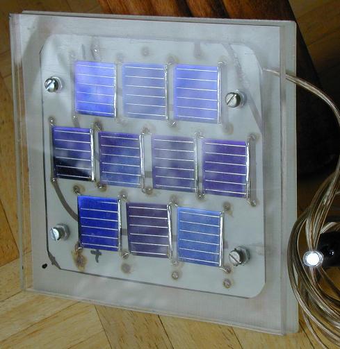
With 7 solar cells, the LED will only light when the PV panel is in bright sunlight. If you use up to 10 solar cells, the LED will light up when the PV panel is in overcast skies. If you use a red, amber, or red LED, the circuit can work with 5 or 6 solar cells since those LEDs operate at a lower voltage.
This circuit could easily be expanded to a higher voltage system by using more LEDs in series and a higher voltage PV panel. A higher current version of the circuit could also be made by using a COB (Chip on Board) LED and a PV panel with larger cells that can produce an appropriate amount of current. Just make sure that the maximum rated LED current value is never exceeded.
For an interesting modification to this circuit, replace the 1000uF capacitor with a 1 Farad/5.5V "Memory Backup Capacitor". An Elna DB-545D105 device was tested on the circuit, after charging up in the sun for a few minutes, the capacitor was able to keep the LED lit for several minutes after the solar panel was shaded from the sun.
Cut the two pieces of plexiglass and one piece of perforated circuit board so that they are slightly wider than the solar array. Drill four holes in the board stack to hold the mounting screws. Mount the solar cells on the perf board and solder them into a series string. An easy way to do this is to solder short segments of thin hookup wire to each cell, route the wires through the perf board and solder the ends on the bottom. When soldering wires to the solar cells, use thin wire and be very quick with the soldering iron to avoid damaging the cells with heat. Connect two wires to the ends of the series string of cells and secure the wires to the circuit board.
If the solar panel is to be used outdoors, seal the edge of the panel with silicone caulk or some other water proof material. Seal the mounting screws where they pass through the plexiglass and seal the output wiring.
When the project is finished, the center circuit board will be spaced away from the front and back plastic panels with extra nuts acting as spacers on the mounting screws. This will leave an air gap above and below the circuit board so that there is room for the solar cells and wiring. Note that the plexiglass layer will reduce the output current from the solar panel, changing the layer to glass would improve the output.
Connect the LED and capacitor in parallel, wire them across the two power leads. Be sure to get the polarity correct, otherwise the LED won't light up. Solder the parts together. Be sure to heat-sink the LED leads while soldering, LEDs can be easily destroyed by overheating the leads.
Place the solar panel in the sun, the LED will light. The photo at the top of this page shows the circuit operating indoors on a cloudy day. If you put the LED on the end of a long wire, it can be placed in a remote location, such as a basement room. As long as there is a moderate amount of light in the sky, the LED will light up. To get the best orientation for the panel, aim it directly at the sun at noon during March or September in a location that is free from shade.
7-10x photovoltaic cells, rated at 15-25ma each.
1x white 25mA LED, high efficiency types work best.
1x 1000uF 15V (or greater) electrolytic capacitor.
1 piece of perforated or printed circuit board.
2 pieces of clear plexiglass.
28 gauge tinned hook-up wire.
24 gauge 2 conductor speaker wire.
miscellaneous screws, nuts and washers.
silicone caulk (optional).
Back to FC's LED Circuits page.