CirKits sells solar power circuit board kits.
(C) 2006, G. Forrest Cook
When connecting a solar panel to a rechargeable battery, it is important to use a charge controller circuit to prevent the battery from overcharging. Charge control can be performed with a number of different circuit types. Low-power solar systems can use a series analog charge controller (voltage regulator), an example is shown as the upper part of my solar powered reading lamp project. Higher power systems can use a series switching charge controller, such as my SCC3 design. Very large systems, such as grid-tied installations, often use a maximum power-point (MPPT) charge controller. This shunt-mode circuit is best suited for low-power systems with a PV charging current of up to 1 amp.
Series regulators (both analog and switching) control battery charging by interrupting the flow of current from the solar panel to the battery when the battery reaches a preset full voltage. MPPT controllers use controllable switching regulator circuits to convert PV power to high voltage and back down to lower voltages, they are complicated and require a bit of power to operate, but offer excellent efficiency which can be beneficial for high power systems.
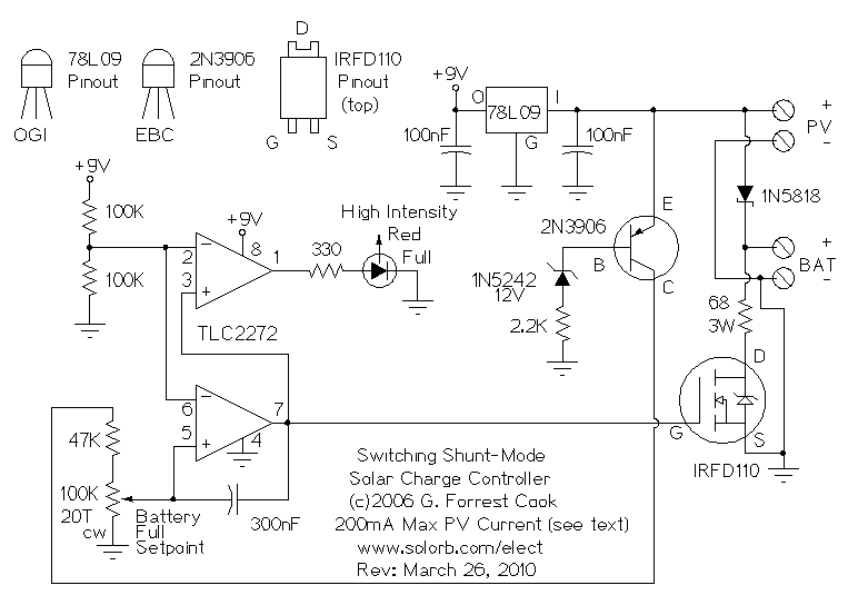
This circuit is a switching shunt-mode charge controller. In a shunt-mode circuit, the solar panel is connected to the battery via a series diode. The diode prevents battery current from flowing back through the PV panel at night. When the solar panel charges the battery up to the desired full voltage, the shunt circuit connects a resistive load across the battery in order to absorb the excess PV charging current. An alternate but similar approach to this switching shunt-mode PV regulator is the Analog Shunt-Mode circuit.
The main advantage of shunt-mode over series mode regulation is the lack of a switching transistor in the power path between the solar panel and battery. Switching transistors are non-perfect devices, they waste a percentage of the available solar power as heat. Inefficiency in the shunt-mode controller's switching transistor does not effect charging efficiency, it only turns on when excess power is purposely being wasted. The main disadvantage of a shunt-mode regulator is that the load resistor value needs to be set to match the amperage provided by a particular type of PV panel. This makes it harder to design as a general-purpose device. Also, for higher current designs, the load resistor becomes large and expensive.
Another difference between series-mode and shunt-mode regulators is the load that the power source (PV panel) sees. In series controllers, when the battery reaches the full point, the power source current path is opened up. In shunt-mode controllers, the power source is always presented with a load.
Shunt-mode regulators are often used for regulating DC-output wind generators and water turbine generators, although this circuit would only work with a very low power generator such as the type used for a science fair demonstration. See my WGR1 12 Volt Wind Generator Regulator circuit for a practical high power circuit.
Solar Panel Open Circuit Voltage: 18V (36 cells)
Solar Panel Short Circuit Current: 200mA max (up to 1 A with a different load resistor).
Battery Voltage: 12V (nom.)
Battery Capacity: 0.1 to 20 Amp-Hours
Solar current is routed from the PV panel through the 1N5818 Schottky diode to the battery. When the battery reaches the full setpoint, the circuit turns on the IRFD110 MOSFET transistor and the the 68 ohm 3W dump load resistor is connected across the battery, absorbing the unneeded charge current.
The 78L09 IC provides 9V regulated power for running the comparator circuitry. Operational power for this circuit is provided entirely from the PV panel, there is virtually no power taken from the battery at night. The two 100K resistors in series provide a regulated 4.5V reference point for use by both comparator circuits. The 2N3906 transistor is wired with a zener diode in its base circuit. When the PV voltage is above 12V, the 2N3906 transistor turns on and enables the comparator circuit. This stabilizes the comparator circuit in low-sunlight conditions.
The battery voltage is scaled down by the 47K resistor and 100K potentiometer. The lower half of the TLC2272 dual op-amp compares the scaled down battery voltage to the 4.5V reference voltage. When the battery voltage is above the full setpoint voltage, the lower op-amp's output goes high and turns on the IRFD110 MOSFET which connects the dump load resistor This activates the IRFD110 MOSFET transistor and the dump load resistor. It is important to use a rail-to-rail op-amp such as the TLC2272CP here, standard op-amps will not turn the MOSFET fully on and off.
When the load across the battery causes the battery voltage to drop, the comparator circuit turns back off. This oscillation continues while solar power is available. The 300nF capacitor across the op-amp slows the oscillation frequency down to a few hertz.
The upper half of the TLC2272 op-amp inverts the dump load control signal, and acts as a buffer for driving the high intensity red LED. The LED turns on when the battery reaches the full setpoint. The LED does not waste any useful charging power since it only turns on when the battery is full, this is a useful feature since this charge controller is designed for low power systems.
It should be possible to modify this circuit to run at more than 1 Amp, although your author has not tried this. A series-mode controller such as the SCC3 is a better choice for higher current PV systems. Higher current operation would require replacing the 1N5818 diode, the dump resistor and IRFD110 MOSFET with higher power components. The value of the dump load resistor should be adjusted, as explained below, to keep the battery voltage below the full point.
Caution should be used when constructing high power versions of the circuit. If any of the components in the shunt circuit were to open up, the battery could become overcharged and may even rupture or explode. Experimenters assume all liability for their work, be careful out there.
It is necessary to match the load resistor to the output of the power source. The 68 ohm resistor shown in the schematic is a good match for a 200mA PV panel. To tune the circuit for a 1 amp PV panel, the dump resistor should be able to handle 1 amp at the battery full voltage. For a 13.8V battery full voltage, the dump resistor should be rated at 13.8 ohms and 13.8 Watts or higher. A 13 ohm/20 Watt resistor would be a practical value to use. If the load resistor is connected directly across the PV panel at noon on a cool and sunny day, the resistor value should be set so that the PV output voltage drops to just below the battery's desired full voltage.
Connect the PV panel to the PV inputs and a rechargeable 12V battery to the battery outputs. The battery should be pre-charged for easiest alignment. Point the panel at the sun, and monitor the battery voltage with a meter. Adjust the 20 turn 100K potentiometer until the Full LED starts to flash, then tweak the potentiometer until the battery reaches the desired full voltage. If the battery is not completely charged, it may take a while for it to charge to the point where the LED flashes.
Place the PV panel in the sun, when the battery reaches the full setpoint, the LED will start to flash with short on-pulses and long off times. As the battery charging continues, the LED flashing will change to long on-pulses and short off times. In cold climates, it may be useful to use the load resistor's heat to keep the battery warm. The load resistor and the battery can be mounted inside of an insulated container. Important: A suitably rated fuse should always be placed between the battery's positive terminal and the rest of the circuitry.
Back to FC's Solar Circuits page.