(C) 2007 G. Forrest Cook
This is a solar-powered white LED lamp with automatic dark-on activation. It can be used for both indoor and outdoor night-light applications. The circuit features selectable Off, On and Auto settings, a built-in photovoltaic charge controller and a low voltage disconnect circuit which helps to achieve a longer battery life.
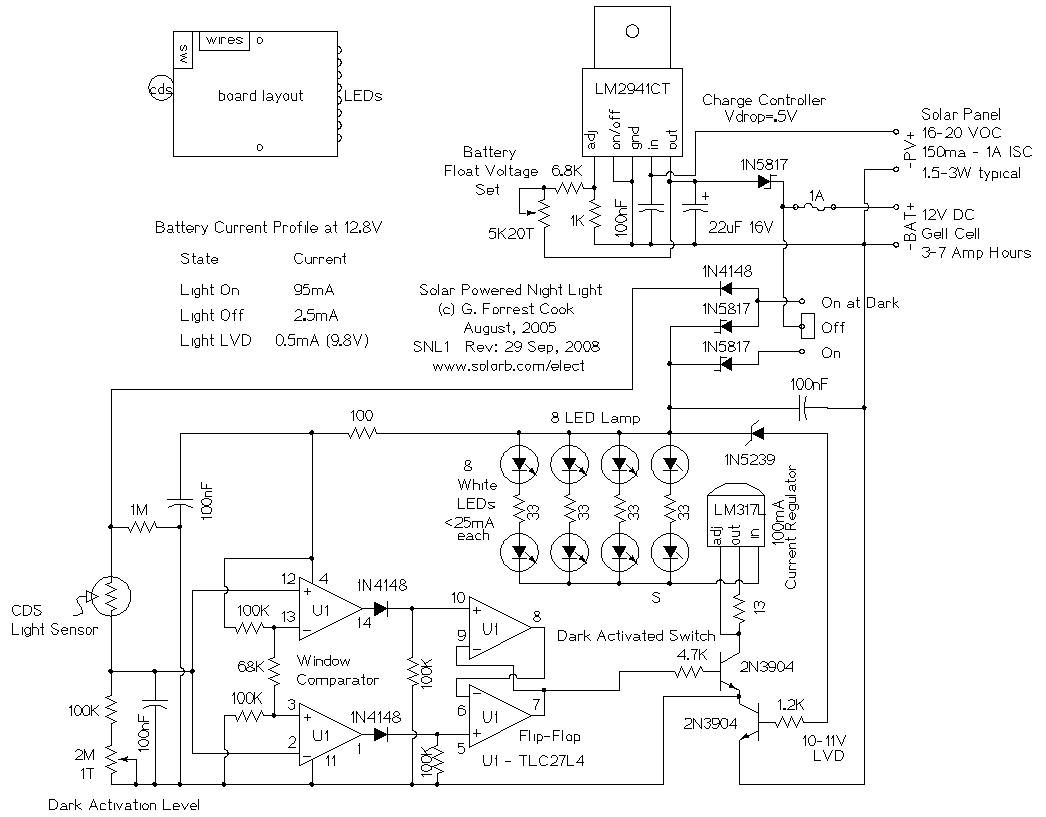
Nominal system voltage: 12V DC
LED on current draw: 95mA
LED off current draw: 2.5mA
Battery drain below low voltage disconnect: 0.5mA
Solar panel current rating: 150mA to 1A ISC
Solar panel voltage rating: 17-20 VOC (36 to 40 cell)
Battery rating: 12V nominal, 1 to 10 Amp hours
Battery type: rechargeable lead acid gell cell, NiMH, NiCD
An LM2941CT low dropout voltage regulator is used as the solar charge regulator. The IC passes solar power to the rechargeable battery until the charge voltage setting is reached, after that point, the regulator limits the charge current to maintain the charge voltage setting (float voltage). The 1N5817 Schottky diode between the LM2941CT and the battery + terminal prevents battery from discharging through the charge controller at night.
The on/off/On At Dark switch selects the mode of operation. When On, battery power is routed to the lamp circuit, but not to the CDS photo sensor, simulating a dark room. The LED lamp turns on. When in the On At Dark position, battery power goes to the lamp circuit and the CDS photo sensor, the LED lamp turns on when the CDS sensor is dark.
The CDS photo sensor is in series with a 2M potentiometer and a 100K resistor. The signal at TLC27L4 pins 2 and 12 changes voltage with varying light levels on the CDS photo sensor. The left two TLC27L4 op-amp sections form a window comparator circuit with hysteresis. The outputs of the two comparators are fed to the right two TLC27L4 op-amp sections through two 1N4148 diodes.
The right two TLC27L4 op-amp sections form a set/reset flip-flop circuit. The flip-flop turns on at a particular darkness, then turns off at a brighter level due to the circuit's hysteresis. This operation lessens the tendency for the circuit to flicker on and off at the trigger point. The TLC27L4 op-amp is a rail-to-rail device, if you substitute another op-amp, make sure it is capable of rail-to-rail operation.
The on/off signal from the flip-flop is sent to the upper 2N3904 transistor, which switches power for the LED lamp circuit. The lower 2N3904 transistor is wired with a Zener diode on its base to form a low voltage disconnect circuit. This causes lamp power to drop off as the battery reaches its fully discharged point and prevents the battery from being totally discharged, giving it longer life.
The LM317L voltage regulator is wired as a series current regulator for the LED lamp, the 13 ohm resistor sets the current to 100mA. Each of the four LED strings receive about 25mA of current from the current regulator.
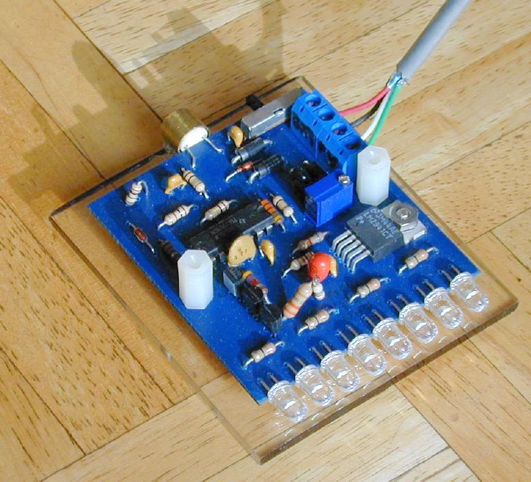
The circuit can be built on a perforated circuit board with hand-wiring techniques, or on a home-made circuit board. If the circuit is operated outdoors, care should be taken to prevent water from reaching any of the electrical connections. The CDS cell should be placed in a dark open-ended tube to shield it from stray light coming from the LED lamps. If too much LED light is reflected back to the CDS cell, the circuit will blink in dim light conditions.
Connect a solar panel and battery to the circuit, put the solar panel in the sun and allow the battery to charge. Adjust the 5K potentiometer on the LM2941CT circuit until the battery voltage is at the desired float voltage. A lead acid gell cell battery can typically be floated at around 13.8V. It may be necessary to let the battery charge for a while before it will reach the upper float voltage setting.
Set the circuit in a dark location and adjust the 2M potentiometer until the LED light array turns on. You may want to fine tune this adjustment so that the LEDs turn on at a particular darkness level.
Install the circuit in the desired location, be sure that the CDS cell does not see a lot of reflected light from the LED lamp. The solar panel should be mounted in a location where it receives full sunlight for some or all of the day.
To use the light manually, put the switch into the ON position. To run the light in automatic mode, put the switch into the On At Dark position. To turn off the light, put the switch into the OFF position.
For a more powerful dark activated switch circuit, check out the DAS1, a DAS1 kit is available.
Back to FC's LED Circuits page.