(C) 2002-2003, G. Forrest Cook
This project can be used with a CirKits solar circuit kit.
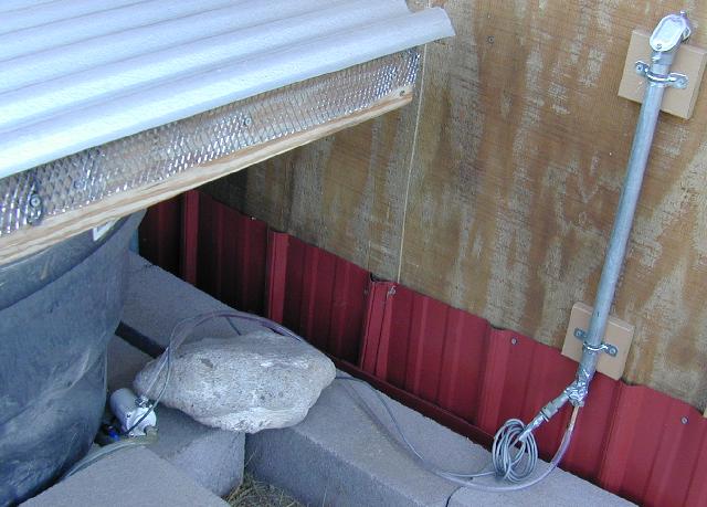
The 12V pump on the side of the cistern
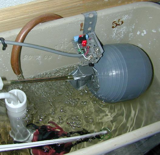
The rev 1 circuit in action
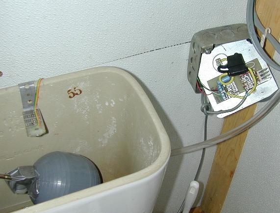
The rev 2 circuit board and sensor
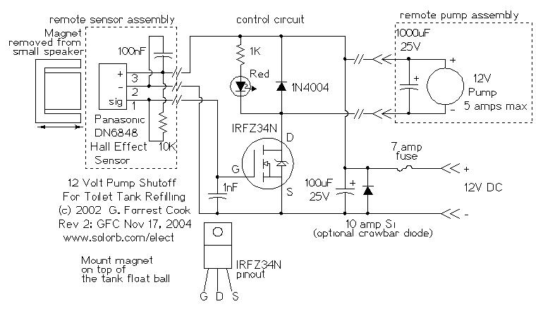
The schematic
A flushing toilet is something that most city dwellers take for granted, but it can be a luxury for those who live far away from utility water and electricity. This circuit controls a small 12 Volt pump that is used to fill a toilet tank from an external rainwater (grey water) collection cistern. A 12V automotive windshield wiper pump supplies the water pressure for this system.
The 12 Volt power in this setup comes from a small solar power system, it may also be provided by a suitable wall-wart DC power supply. The cistern is located below the toilet tank, the pump moves the water up to the toilet's tank. The pump is switched on when the toilet tank is empty, it is switched off when the tank has filled.
Nominal operating voltage: 12V
Idle current: < 1 ma
Pump Current: < 5A
The Panasonic hall effect sensor is the heart of the system. The hall effect sensor's output pulls to ground when in the presence of a relatively strong magnetic field. When the magnet is pulled away from the hall effect sensor, the output goes high via the 10K pull up resistor. This turns on the IRFZ34N MOSFET transistor, which pulls the negative lead of the 12V pump to ground, turning on the pump and the red LED.
A 100nF capacitor is connected from pins 2-3 on the hall effect sensor to reduce the chance of the sensor picking up stray radio signals. A 1nF capacitor capacitor is connected from the IRFZ34N gate to ground, it also filters out potential radio frequency interference.
The 1N4004 diode across the pump snubs out inductive voltage spikes from the motor, the 1000uF capacitor across the motor eliminates motor brush noise from the DC wiring. The 100uF capacitor on the power input filters noise from the 12V power source. As with all electrical circuitry, it is important to have a fuse and a switch in series with the power source, the switch is not shown in the schematic.
The 10 amp silicon diode is used in a crowbar circuit. Its purpose is to protect the circuit from reverse DC polarity on the power terminals. Reverse polarity causes the fuse to blow.
This circuit will work with most momentary action (non-latching) hall effect sensors, you may want to experiment with the sensor and magnet to find the most sensitive orientation for both parts.
The rev 1 version of this circuit had all of the parts inside of the toilet. This turned out to be a bad idea as water splashed onto the board and electrolysis corroded the electrical connections.
Rev 2 involved splitting the circuit into two parts, the hall effect sensor assembly and the rest of the electronics. The hall effect sensor was soldered to a small piece of circuit board, that was then screwed onto a piece of plumbing strap. The entire sensor assembly was coated in epoxy glue to make it waterproof. Silicone sealant would also work well as a sealant, just be sure to let the silicone cure for a few days before applying power.
The rest of the circuit was hand-wired on a scrap piece of prototype circuit board, that was mounted on a cover plate for a standard 4"x4" electrical box. A small aluminum heat sink was screwed onto the IRFZ34N MOSFET. Wires from the box connect to the sensor, the pump motor and the 12V supply.
The magnet was connected to the toilet tank float with duct tape. A better magnet mount could certainly be fashioned, but this arrangement has held up for many years. Sometimes it is necessary to cheat when working in the field. The magnet was removed from an old miniature speaker. The voice coil gap around the magnet's pole-piece was filled with silicone sealant to prevent rust. People in damp climates may want to coat the entire magnet with epoxy paint or silicone caulk.
The output of the cistern tank is sent to a shutoff valve, a plumbing reducer assembly and a coarse water filter. The rest of the external plumbing can be built with 3/8" flexible plastic tubing and secured with hose clamps.
The water filter can be made with a 4" piece of 1" I.D. threaded PVC pipe and two PVC end caps. Holes should be drilled into the end caps and short pieces of 3/8" copper tubing should be epoxied into the holes. Metal window screen should be rolled up and stuffed into in PVC pipe.
The pump inlet port is connected to the filter output with a short length of 3/8" plastic tubing. The pressurized water stream from the pump's outlet port travels through another piece of 3/8" plastic tubing and into the building. The flexible tubing connects to a 1' piece of bent copper tubing that snakes under the toilet tank lid. The output side of the copper tubing should be above the tank's full water level to prevent back-siphoning.
The pump output tube and wiring is built with connectors so that the pump can be removed when the building is unoccupied. A more permanent installation can be done by mounting the pump in a metal box on the side of the building.
Bend the metal strap that holds the sensor board so that the hall effect sensor is directly above the magnet. Adjust the height of the PC board so that the circuit shuts off at the desired water level.
Flush the toilet, the red LED will light up, and the pump will move water into the toilet tank. As soon as the water level reaches the top, the pump will shut off. Just like in the city. If you want to use this device in an area where the temperature gets below freezing, the water supply, pump, and water tubing will need to be mounted in an area that does not freeze, such as underground or indoors. This circuit has been in use for many years, it sure beats hauling buckets of water from the rainwater collection system to the toilet tank.
This setup can be very useful for people living in off-grid houses, even if the house has a pressurized water system. It takes a large amount of energy to fill up a water pressure tank and a toilet can use a lot of water. By using rain water and a small pump to supply toilet flushing water, it is possible to greatly reduce the amount of pressurized water that is used. This reduces the daily energy load on the house battery system and will result in a longer lifetime for the battery.
The pump input filter should be disassembled and cleaned out when it becomes filled with debris. Cleaning time will be signalled when the tank refilling time increases. The cistern will also tend to collect debris, it should occasionally be stirred up and dumped out.
I have gone through a number of different pumps, mostly due to operation at temperatures below the freezing point of water. Applying power to a frozen pump will cause the pump motor to burn out. The rest of the circuit has managed to survive this abuse, a properly sized fuse may protect the motor from this problem.
A useful revision to this circuit would be to include a cut-off circuit that prevents the motor from running when the outside temperature drops below freezing. This problem was greatly reduced by moving the pump indoors to a location where the pump did not freeze. Freezing of the supply tube is still an issue.
Another failure can occur if the supply tank runs dry. In this situation, the pump will run continuously and the motor commutator will eventually wear out. This problem could be corrected by either adding a pressure switch to the water line, or adding a timer that shuts off the motor power after a few minutes of operation.
A 12V automotive windshield wiper fluid pump is suitable for use with this circuit. These can be found on eBay or at an automotive junk yard. A "universal replacement" style of windshield washer pump can often be found at an auto parts store, such a device is suitable for this application.
Back to FC's Solar Circuits page.