This project can be used with a CirKits solar circuit kit.
This circuit was featured in Home Power Magazine #69
(C) 1998, G. Forrest Cook
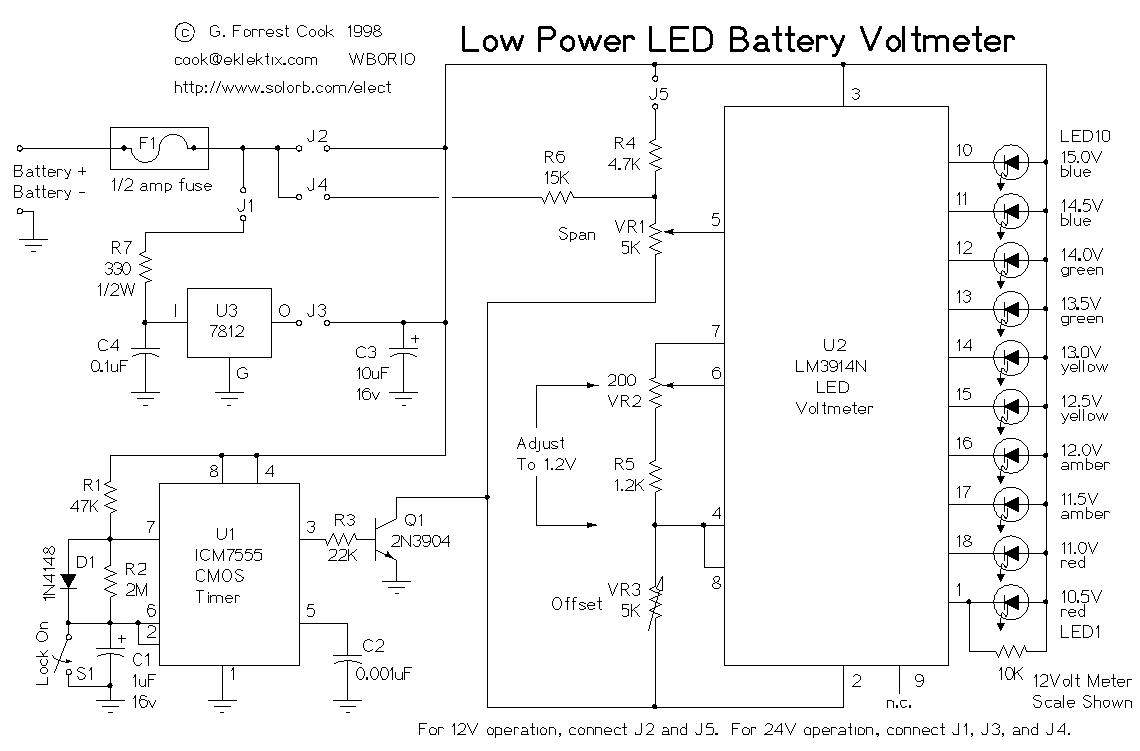
This is a low power voltmeter circuit that can be used with alternative energy systems that run on 12 and 24 volt batteries. The voltmeter is an expanded scale type that indicates small voltage steps over the 10 to 16 volt range for 12 volt batteries and over the 22 to 32 volt range for 24 volt batteries. Power consumption can be as low as 14mw when operated from 12V and 160mw when operated from 24V.
This meter design has been updated and is now part of the 12 Volt Battery Voltage Monitor (BVM1) project, kits are available from CirKits.com.
It is possible to set the meter to read equal steps across a variety of upper and lower voltages. The meter saves power by operating in a low duty-cycle blinking mode where the LED indicators are only on and consuming power briefly during a repeating 2 second cycle. The circuit may be switched to a high power mode where the active LED stays on at all times.
Different colored LEDs may be used for the voltage level indicators, this allows the battery state to be read in the dark. With blue LEDs, it is possible to have a nice looking rainbow of colors using two each of red, amber, yellow, green, and blue LEDs. The circuit will also work with inexpensive and common red LEDs. If the circuit is to be used in sunlight, ultra-bright LEDs should be used.
Typical uses include the monitoring of portable battery operated systems and indoor wall mounted home power system charge indicators. The circuit can be built for under $20 (US), all of the parts are commonly available.
The circuit may be built with either the CMOS ICM7555 timer or the more common bipolar 555 timer. The 7555 timer will provide much more efficient operation and should be used for systems with small batteries.
		7555timer(12V)  555timer(12V)  7555timer(24V)  555timer(24V)
Idle current:	0.34ma		6.1ma		6.3ma		24ma
LED ON current:   18ma		22ma		12ma		28ma
Average current: 1.2ma		6.9ma		6.6ma		24ma
Average power:    14mw		83mw		160mw		580mw
Duty Cycle: Approximately 5%
Blink Frequency: approximately 0.5hz
Operating Voltage: 10V - 20V (12 volt model) 20V - 35V (24 volt model)
Nominal Scale: 10.5V to 15V in 0.5V steps or 22V to 31V in 1V steps
The heart of the circuit is the LM3914N dot-bar volt meter IC, U2. This chip is operated in the expanded-scale mode so that the circuit responds in the 10-16V range.
U2 outputs a steady voltage on pin 7 from the internal voltage reference. This is fed via voltage dividers VR2 and R5 to the internal reference input pins to set the range that the meter is sensitive to. The measured voltage is fed in on pin 5 via the voltage divider consisting of R4 and VR1. This divider scales the input voltage down to a range that is useful to the IC.
The basic expanded 12 volt scale LM3914 voltmeter circuit was published in Nuts & Volts magazine (1), a similar circuit was shown in Home Power #10 (2).
The U2 positive supply is connected to pin 3 which is nominally 12V. The U2 negative supply is switched on momentarily via transistor Q1, this switching action is what makes the circuit efficient since U1 (ICM7555) consumes a mere 0.34 ma while U2 consumes around 18ma with one LED on. The ICM7555 timer, U1 is wired to run in an astable (free-running) mode with a narrow pulse width square wave output.
The duty-cycle of U1 is controlled by the ratio of R1 and R2. R2 may be adjusted to a smaller value if faster blinking is desired, a potentiometer may be substituted for R2 if a rate adjustment is desired. R1 may be increased if a longer on-time is desired. Changes in R1 and R2 will affect the average current that the circuit consumes. The frequency of oscillation is determined by C1, R1, and R2. C1 may be either an electrolytic or poly capacitor, if an electrolytic part is used, be sure to connect the positive terminal to U1 pins 6 and 2 and the negative terminal to ground.
The output of the timer IC is fed through current limiting resistor R3 to transistor Q1 which controls power to U2. Capacitor C2 filters the control voltage input to U1 and capacitor C3 provides DC filtering for the whole circuit. When the lock-on switch across capacitor C1 is closed, the output of the timer remains on, thus enabling the U2 circuitry and increasing the current drain to 18ma. The reason the switch is not simply wired across the transistor is to keep the negative supply to U2 the same as when the circuit is pulsed on. This maintains the same calibration on the LEDs in both modes because the transistor's voltage drop is always part of the circuit.
Last, but not least, fuse F1 protects against the potential for fire hazard should the circuit become shorted out. The average current is calculated by adding the constant current required by U1 with the product of the current from U2 times the duty cycle, see the specifications for details. To operate the circuit in the 12V mode, wire the circuit so that jumpers J2 and J5 are shorted, parts U3, C4, R6, and R7 may be left out.
When wired for 24 Volt operation, the meter responds in the 20-32V range. R6 is connected to the 24V supply instead of R4, the greater value of R6 scales the higher input voltage to a range that is useful for U2. Voltage regulator U3 with series resistor R7 scales the 24V down to a regulated 12V to provide the proper operating voltage for the ICs. Resistor R7 assures that the input voltage to the regulator stays well below the 35V absolute maximum specification of the IC. Operation in 24V mode is less efficient than in 12V mode because of the extra power dissipated by the voltage regulator and R7. To operate the circuit in the 24V mode, wire the circuit so that jumpers J1, J3, and J4 are shorted. R4 may be left out in the 24V mode.
I built the prototype of the circuit on a 2"x3"copper plated PC board, the chips were installed in wire-wrap sockets which were glued to one side of the circuit board. The parts were soldered to the back of the wire-wrap socket pins. The coper was used as the ground plane and all ground connections were soldered directly to the board. The LEDs were arranged in an array on a separate piece of perforated circuit board and were wired back to U2 using wire-wrap wire. If you solder to the LEDs, be sure to connect a heat sink clip to the LED pins before soldering, LEDs are easily destroyed by excess heat. The perforated LED board was mounted to the main circuit board using spacers and machine screws. The 7555 timer and the blue LEDs are static sensitive, avoid zapping these or any of the other semiconductor parts with static electricity.
Beginners should probably use a larger piece of circuit board to start with as wiring was very tight. Drill any mounting holes in the circuit boards before connecting the parts. Thin gauge electronics solder was used and an electronics soldering iron of the 30 watt variety should be used. Voltage readings may be printed or drawn on a piece of paper and placed next to the LEDs.
It will be necessary to have an adjustable regulated DC power supply and an accurate volt meter to perform the alignment. Follow these instructions for the 12V version of the circuit.
Close switch S1 so that the LEDs stay on. The first step of alignment involves setting the reference voltage for U2. Connect the external volt meter across U2 pins 6 and 4 and adjust VR2 for a reading of 1.2 volts. Center the settings of VR1 and VR3. At this stage, you should decide what scale you want the meter to read. I was able to adjust the circuit to read 0.5V steps between 10.5V and 15V as well as 0.3V steps between 10.5V and 13.2V. For this example, the circuit will be set up to use a 10.5 to 15V scale. The span between the end points is 4.5V.
Adjust the power supply from 9V to 15V and see where the meter is reading, it may not read at all until the potentiometers are near the right range, if this is the case, set the power supply to 12V and adjust VR3 until one of the center LEDs light. Adjust the power supply until the first LED just comes on, measure that voltage. Adjust the supply up until the last LED just comes on, measure that voltage and subtract the first voltage, this is the span. Adjust VR1 and repeat the previous adjustment until the span is 4.5V. Now set the voltage to 10.5V and adjust VR3 until the lowest LED just turns on. VR1 and VR3 interact so it may be necessary to perform the adjustments a few times to get it perfect.
To align the 24 Volt version of the circuit, it will be necessary to have a variable power supply that can be adjusted up to around 30V. A good method for achieving a higher voltage adjustable supply is to put a charged 12V battery in series with a lower voltage variable supply. As always, when dealing with high current sources such as batteries, use fuses in the wiring and insulate exposed connections.
Connect the appropriate voltmeter circuit across a 12 or 24 Volt battery and observe the blinking LED for a battery voltage indication. Activate switch S1 for a constant on display. If the voltage is higher than the top step, the highest LED will remain on. If the voltage is lower than the bottom step, all of the LEDs will stay off. The prototype version of this circuit has been in continuous use for over 7 years, the design has passed the test of time.
U1:		ICM7555 CMOS timer IC (Harris/Intersil)
U2:		LM3914N LED voltmeter (National Semiconductor)
U3:		7812 12 Volt regulator (National Semiconductor)
Q1:		2N3904 NPN silicon transistor
D1:		1N4148 silicon switching diode
LED1-LED10:	Red, yellow, amber, green, and blue LEDs in any
		arrangement, see text.
C1:		1.0uF capacitor, electrolytic may be used.
C2:		0.001uF ceramic disk capacitor
C3:		10uF electrolytic capacitor
C4:		0.1uF ceramic disk capacitor
R1:		47K 1/4W resistor
R2:		2M 1/4W resistor
R3:		22K 1/4W resistor
R4:		4.7K 1/4W resistor
R5:		1.2K 1/4W resistor
R6:		15K 1/4W resistor
R7:		330 ohm 1/2W resistor
VR1, VR3:	5K trimmer potentiometer, 10 turn style
VR2:		200 ohm trimmer potentiometer, 10 turn style
F1:		1/2 Amp DC fast blow fuse
S1:		miniature toggle or pushbutton switch

(1) Electronic Q&A Column, T J Byers, Nuts & Volts magazine, July 1997
(2) Home Power Magazine #10, Richard Perez
For an interesting effect, each LED in this circuit can have a unique color, see my 13 Color LED Rainbow circuit for color ideas.
Back to FC's Solar Circuits page.