(C) 2005, G. Forrest Cook
This project can be used with a CirKits solar circuit kit.
This circuit is used to measure the voltage on a 12V (nominal) lead acid rechargeable battery system. It was specifically designed for use in solar powered systems but is general enough that it can be used for automotive or other 12V systems.
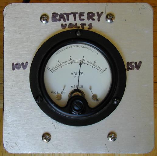
Lead acid batteries normally spend their working lifetime in the voltage range of 11-15 Volts. This meter circuit was designed to show the voltage range of 10-15V on an analog meter movement, it can be used to show the battery charge state from empty to full.
Measured Volts: 10-15 Volts DC
Circuit Current: 9.2mA at 15 Volts DC input
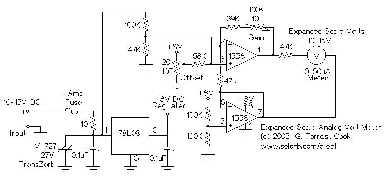
The input voltage is filtered from transient voltage spikes via the 10 ohm resistor and the 0.1uF capacitor on the input of the 78L08 regulator. The 1 Amp series fuse and Transzorb protect the circuitry from short circuits and over-voltage conditions.
The 78L08 voltage regulator provides a constant 8V DC supply to the meter circuitry through the 10-15V input voltage range. The dual op-amp is supplied with 0V and 8V for the power rail inputs. The lower op-amp is set up as a buffer stage to provide a 4V virtual ground reference voltage. The virtual ground is used as a current sink for the meter, and as a reference point for the other op-amp.
A 78L08 regulator may be a difficult part to find, a good replacement would be an LM317L adjustable regulator circuit set to 8V. Other dual op-amps should work well in this circuit, the 1458 is a good substitution, an ultra-low power dual op-amp can be used if power drain is a consideration.
The upper op-amp is configured as a voltage summing circuit with adjustable gain. Gain is controlled by the 100K feedback resistor. The gain control adjusts the meter sensitivity across a voltage range. The measured voltage comes into the upper op-amp's + input via a 100K/47K voltage divider. The offset control creates a second + input voltage that is summed with the measured voltage through the 68K resistor. Adjustment of this control moves the meter position up and down, it is used to set the meter movement at 0 when the minimum measured voltage (10V) is applied to the circuit. The meter shown has a sensitive 50uA full scale reading, more common 1ma meters can be used by reducing the value of the 47K meter series resistor to 2.5K.
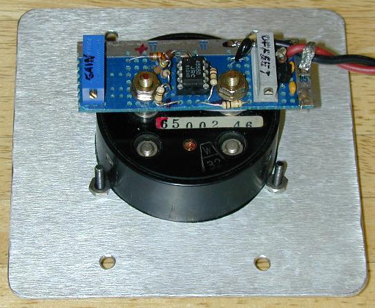
An approximately 1"x3" piece of perforated circuit board material was drilled with two holes so that the board could be mounted on the two terminals of the analog meter. The parts were assembled on the perforated board and connected together with point-to-point wiring. Teflon insulation was used over bare wires to make the cross-board connections. The two battery leads were twisted together, then secured to the edge of the circuit board with a loop of wire to prevent movement.
The meter was mounted on a 4"x4" metal plate that was cut and drilled to fit onto a standard electrical switch box. The box should be deep enough that the meter and accompanying circuit board do not touch the back of the box. Wiring between the meter box and the battery box was run through metallic conduit.
Connect this circuit in parallel with a digital Volt meter for alignment. Both meters should be connected to a stable variable voltage power supply that is capable of operation in the 10-15V DC range. Set the input voltage to 12.5V, set the gain control to midway, and adjust the offset control until the meter reads in the center of its range. While watching the digital meter, move the input voltage to 12.0V. Observe the analog meter position. Adjust the input voltage to 13.0V and observe the meter position again. If the meter swings more than 1V on the dial, decrease the gain control. If it swings less, increase the control.
Repeat this until the meter accurately measures a 1V change. Set the input voltage to 12.5V, adjust the offset control so that the meter shows 12.5V. It will probably be necessary to adjust both controls alternately to get the meter aligned exactly. Observe the meter readings at 10.0V and 15.0V, adjust the controls until it reads the end-point voltage accurately.
Connect the circuit across a 12V battery and observe the voltages. The meter consumes a small enough amount of current that it can be left connected all of the time for all but the smallest of batteries.
Back to FC's Solar Circuits page.