(C) 2003, G. Forrest Cook
This circuit produces two audio frequency sine waves with different frequencies but equal amplitudes. It can be used for testing a variety of audio equipment. The circuit was originally developed the purpose of aligning an FM Stereo Modulator, like the type used in low power FM stereo transmitters. The circuit is also handy for testing computer sound card inputs and tape recorders. If the two tones are combined with a resistive mixer, the resulting signal can be used for testing single sideband (SSB) transmitters.
The low tone has a secondary output that is 180 degrees out of phase with the primary output, this can be used to test circuits with differential inputs. The two primary outputs on the low tone can be used for feeding a mono signal to two channels of a stereo device.
Operating Voltage: 9-12V DC
Operating Current: 15ma at 12V
Low Output Frequency: approximately 600 Hz
High Output Frequency: approximately 800 Hz
Output Levels: approximately 0.5V - 5V P-P
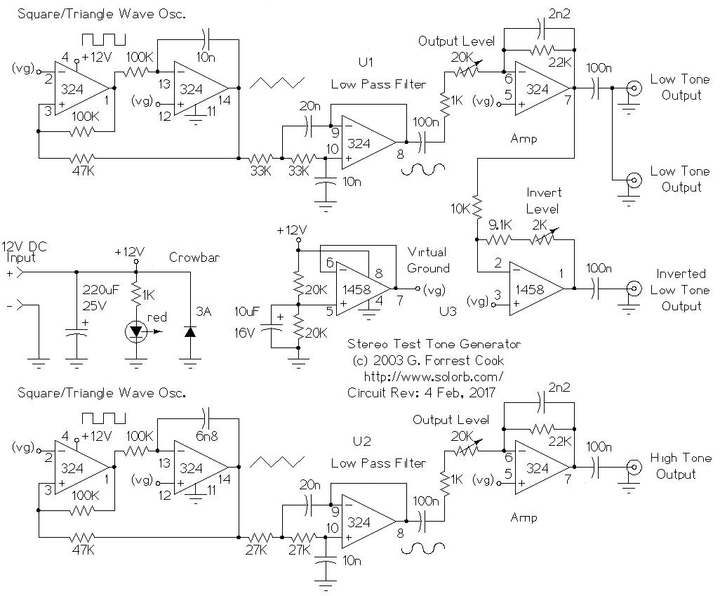
IC U3B is wired to produce a virtual ground at half of the power supply rails (6V). This is used elsewhere in the circuit as a reference. The power supply is filtered with the 220uF capacitor. The 3A crowbar diode offers some protection against reverse polarity on the power inputs. For full protection, place a 1A or smaller fuse in series with the +12V input.
The circuit has two nearly identical stereo sine wave generator circuits. U1 is the low tone oscillator, U2 is the high tone oscillator. The two op-amps on the left of each oscillator chain produce square and triangle waveforms at fixed frequencies. The frequency is set with the 10n and 6n8 capacitors.
The triangle waves are passed into low-pass filters which remove most of the harmonic energy and produce relatively pure sine waves. The two 27K and two 33K resistors set the low pass frequency.
The sine waves are each fed into an output amplifier which can be adjusted for fixed level outputs. The low tone output is also fed into IC U3A which produces an inverted copy of the low tone signal.
The LM324N quad op-amp is a very common and inexpensive chip, however it does tend to produce cross-over distortion when used in analog circuits such as this one. This distortion shows up in the two sine-wave outputs in this circuit. This can be seen on an oscilloscope as a small bump near the midpoints of the sine-wave outputs. Two TL074N quad op-amps were been substituted for the LM324N ICs in this circuit and the cross-over distortion was eliminated with no other circuit changes. The frequencies of the two oscillators increased by a small amount. The TL074N is the recommended replacement for the LM324N for producing cleaner sine wave outputs.
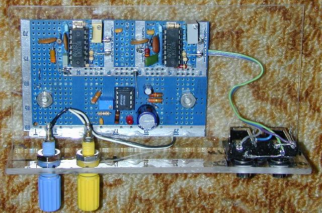
The circuit was built on a piece of perforated prototyping circuit board. Wiring was done by hand using bare tinned copper wire covered with small pieces of teflon insulation. The circuit board and connectors were mounted on a piece of bent plastic, this protects the board from shorting out.
For the best stability, use high quality capacitors for the oscillator and filter sections. A regulated power supply is recommended for powering the circuit.
Connect an oscilloscope to the low tone output and adjust the low tone output level for a specified level, I used 4V peak-to-peak.
Connect the oscilloscope to the high tone output and adjust the high tone output level to the same level as the low tone oscillator.
Connect the oscilloscope to the inverted low tone output and adjust the invert level for the same level as the low tone output. If you have a two channel oscilloscope, connect one channel to the low tone output, connect the other channel to the inverted low tone output. Set the scope to add the channels with one of the channels inverted, then adjust the invert level control for the best null.
If you are using the circuit for precision level setting, verify the output levels prior to each use and adjust if necessary. For most audio work, the alignment only needs performing one time.
To generate sine waves with different frequencies, change the value of the capacitor on the oscillator circuits to different values. The two input resistors on the low-pass filter should also be changed so that the filters attenuate the triangle wave's harmonics and produce a sine wave output at the new frequency. The filter can be made adjustable by replacing the two resistors with a dual 100K potentiometer.
There are three stereo signal combinations that can be generated with this circuit. For a mono test signal, connect both channels to the two primary low tone outputs. For a stereo two tone test signal, connect one channel to the low tone output and the other channel to the high tone output. For a two phase one tone test signal, connect one channel to the low tone output and the other channel to the inverted low tone output.
Back to FC's Music and Audio Circuits page.