(C) 2002, G. Forrest Cook
This article describes a motorized, waterproof mount for a miniature video camera. If a suitable waterproof camera is used, this assembly can be used outdoors.
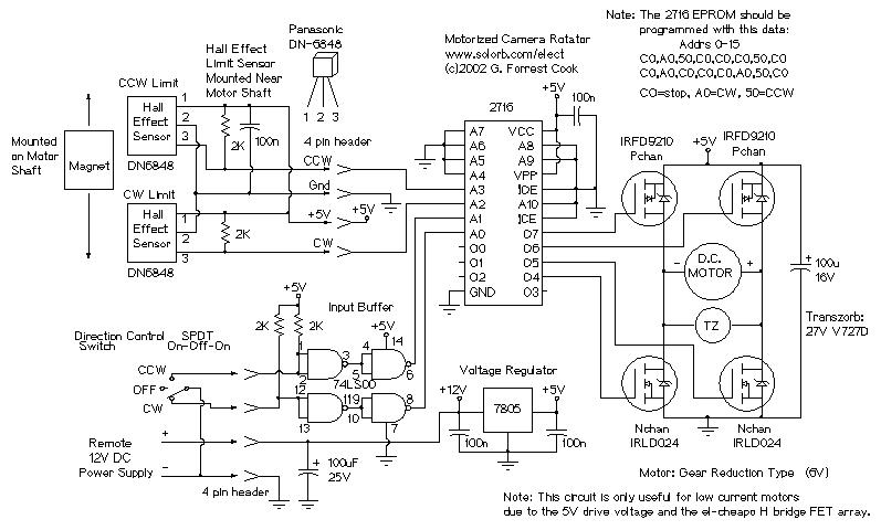
The camera rotator circuit uses a 2716 EPROM to store a table of logic values that control the motor driver (H-bridge) circuit. The EPROM data is shown in the schematic. By using the EPROM, a large number of discrete logic gates can be eliminated. The logic table is designed to allow the motor to turn clockwise until the clockwise limit sensor is reached and counter-clockwise until the counter-clockwise limit sensor is reached.
Four bits of input come from the limit sensors and the direction control switch, these go to the EPROM address lines. All of the input signals are low-active. Four EPROM outputs go to the four H-bridge transistor gates. The control switch signals are buffered through the 7400 quad NAND gate, this allows for a long control wire. The control wire should be a shielded type such as beldfoil and the shield should be grounded at only one side.
The H-bridge array consists of two N-channel MOSFETs and two P-channel MOSFETs. Diagonal pairs of transistors are turned on to move the motor one way or the other. If all of the transistors are off, the motor does not move. Note that the P channel transistors turn on with a 0 logic output level and the N channel transistors turn on with a 1 logic output level.
There are several disallowed output states, if the wrong two transistors are turned on, the transistors and voltage regulator would heat up and possibly be destroyed. If the EPROM is programmed correctly, this will never happen.
The voltage regulator produces 5 volts for running the logic ICs and the motor. A higher power H-bridge driver circuit (or IC) could be used if higher motor current is needed. The L298 IC is a common H-bridge driver that can be purchased online, these are available installed on a small circuit board.
Note that a much simpler circuit could be made with a cross-wired center-off DPDT direction switch and mechanical limit sensor switches in series with the motor power wires, diodes would be required across the switches. This circuit has fewer moving parts, and the hall-effect sensors can fit into a smaller space than most switches. The solid state design should also last longer.
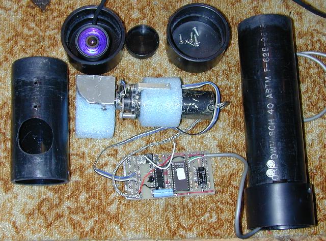
There are two circuit boards used in this project, both were hand-wired. The main board houses the logic circuitry and the motor H-driver VMOS FET array. It was constructed on a piece of perforated bread-board.
The hall effect sensor array was built on a piece of copper PC board. The board was cut to a C shape and holes were drilled in the ends so that the board could be screwed to the motor mount tabs. The two hall effect sensors were glued to the PC board with epoxy glue. Be sure to secure the wire coming from the sensor board with some form of strain relief. Plastic wire ties are suitable for this job.
Both sensors are located an equal distance from the center of the motor shaft. Other sensor board components were hand-wired to the sensors. The sensor board can be seen in the photo, it is mounted on the top of the motor where the shaft exits the motor case. The D-shaped aluminum block has a small but powerful magnet glued to the side that passes directly over the hall effect sensors. The magnets pass within about 1/8 inch over the sensors.
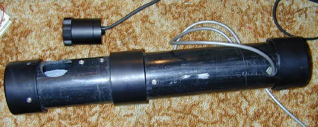
This project involves a fair amount of mechanical work. The tube that holds the camera, electronics, and motor was fabricated with Schedule 40 ABS black pipe. The longer portion (top) of the pipe is stationary, and should be secured to an external mount with hose clamps or other mounts. The top portion consists of a top cap, a long tube with room for the motor and logic board and an ABS pipe sleeve. Glue the sleeve to the bottom of the long pipe. Don't get any glue on the bottom half of the sleeve.
The top cap can be connected to the upper pipe by drilling a small hole through the cap pipe and installing a small stainless steel screw. A small hole is drilled through the upper pipe, this allows the video camera and motor control wires to exit the assembly. When the assembly is complete, seal the wires where they exit with Silicone caulk.
The short lower portion of the pipe houses the video camera. The top inch of the lower portion should be evenly filed around the outside so that it fits easily into the top portion's sleeve. Keep filing until the lower portion of the pipe spins easily in the sleeve. A hole needs to be cut in the lower portion to house the camera. This can be done by drilling small holes, then filing the opening until the camera fits snugly. The hole should be large enough to allow the camera to be adjusted up and down. The camera was secured in the lower assembly using blue packing foam. A pipe cap covers the bottom of the lower assembly.
The camera's wire should pass through the inside of the tube, put a few loops of extra wire near the camera. It is important to verify that the wire does not get hung up on any objects in its path as the camera is rotated.
Water flow should be considered. If the assembly is built correctly, it should be able to withstand blowing rain without getting the electronics wet. A small hole should be drilled in the lower pipe cap to allow any moisture that condenses inside to escape.
Several metal pieces need to be fabricated. A small bracket is needed to connect the motor mount to the side of the upper tube. The size of the bracket depends on the motor that is used. The motor shaft should be exactly centered in the tube when the mount is complete.
The shaft mount piece is a D-shaped chunk of aluminum, a hole was drilled to fit the motor shaft, a side hole was drilled and tapped to hold a set-screw for securing the mount to the shaft. Two mount holes were drilled and tapped into the mount, screws pass through the lower pipe into the mount. The magnet is glued to the bottom of the shaft mount, it should pass right over the hall effect sensors. Test the magnet on the hall effect sensors before gluing them in place, the sensors will only respond to one side (pole) of the magnet.
Make sure that the camera wire does not get hung up on the insides of the camera. This is achieved by adjusting the wire length so that it has some slack when it is at either extreme of its movement. It is advisable to round any sharp edges that are in the area where the video wire rotates.
The hall effect sensors should be tested for proper operation. Make sure that the magnet changes the logic state on both sensor outputs when it passes over the two sensors.
This project was built with surplus parts. The camera is a model GM300K-N from an unknown manufacturer. The motor is a 12 Volt gear reduction unit made by Globe, other similar motors could be used. The electronic components can be found from various online suppliers.
A good place to find hall-effect sensors is inside of old brushless DC computer fans. If power is applied to the disassembled fan circuit, it should be possible to determine which sensor pins are ground, V+ and output using a meter or oscilloscope. Many hall-effect sensors used in fans have dual outputs with opposite polarities, use the output that is low when the magnet is near the sensor. Also note that some fan hall-effect sensors have an automatic pulser circuit for starting the fan motor, that type of sensor should not be used in this project.
Turn the switch to CCW, the camera should rotate couter clockwise until the limit is sensed. Turn the switch to CW, the camera should rotate clockwise until the other limit is reached. Turn the switch off, the camera should stand still.
Back to FC's Video Circuits page.