(C) 2003, G. Forrest Cook

This project is a QRP (low power) antenna tuner (transmatch) for use in the short wave amateur radio (Ham) bands (3-30 Mhz). It allows a wide variety of antennas to be connected to a low or medium power transmitter or transceiver. When the circuit is properly tuned, the maximum transmitter power will be delivered to the antenna. The tuner is normally is used in conjunction with a standing wave ratio (SWR) meter, this meter may be built in to some transmitters. This is an updated version of the circuit, one extra switch has been added to greatly increase the tuning capabilities. See the Original Circuit for reference, note that the photos are from the earlier version of the circuit.
This tuner is fairly efficient and it is very simple to build and use. With the parts shown, the maximum power through the unit is approximately 50 watts. The tuner is small enough for backpacking and is useful for matching many of the types of antennas that one might set up on a camping trip. It can also be very useful at a home ham shack.
The tuner can be used for getting a more perfect impedance match to an antenna that is resonant at or near the frequency that is being used. It is also useful for using an antenna that is designed for one frequency (band) with a transmitter that is set to a different band. Note that it may not be possible to get a good match with every non-resonant antenna. A good rule of thumb is that it is usually much easier to run a lower frequency antenna with a higher frequency transmitter than vice versa. The tuner works well at matching antennas that are resonant at odd sub-harmonics such as a 7 Mhz antenna being used at 21 Mhz.
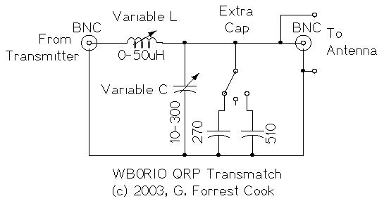
The purpose of a transmatch is to match the impedance of a transmitter, typically 50 ohms, to an antenna system with a different impedance and reactance. A transmatch can add series or parallel capacitance and inductance to produce a more resistive (non-reactive) load to the transmitter. The circuit in this transmatch consists of a variable inductor in series with a variable capacitor (L-network). The transmitter typically connects to one end of either the variable capacitor or the variable inductor. The antenna connects to the junction of the inductor and capacitor. The input and output connections can be swapped for more matching possibilities.
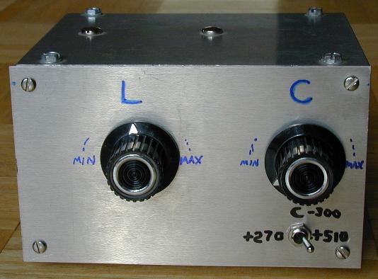
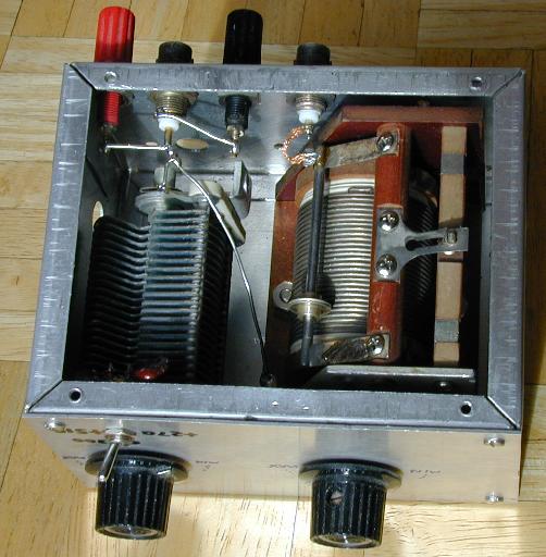
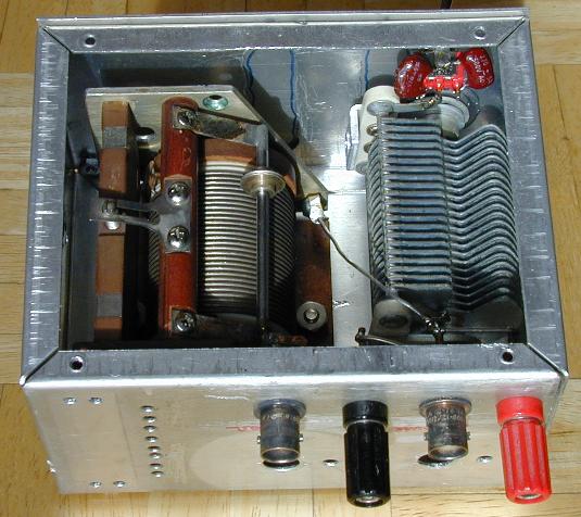
The tuner was built into an old aluminum project box that had been used for at least one prior project as indicated by the numerous holes. This box was just large enough to hold this tuner circuit, a larger box would make construction easier. A rectangular piece of aluminum was added to the front of the box to cover up some of the old holes. Several new holes were drilled in the box for mounting all of the components required by this project.
When laying out the parts, it is a good idea to leave room around the sides of the variable coil and capacitor to prevent RF arcing. Be sure to keep both sides of the variable inductor insulated from the box, you may need to use insulated bushings (non-conductive washers) on the inductor's shaft. The variable capacitor should also be isolated from the box, insulated washers were used to mount the capacitor's shaft to the box. Insulated shaft couplings can also be used if you have them. Use heavy hook-up wire to connect the various components together, 18 gauge or heavier tinned copper wire is recommended. Use the shortest wire lengths possible. Teflon insulation can be used on the wires, although it is optional.
Connect the transmitter output to an SWR meter, connect the SWR meter output to the input of the antenna tuner, and connect the antenna to the output of the tuner. An SWR meter that has two meter elements is much easier to use than one with a forward/reverse switch and a single meter element. Antennas with a coaxial feedline can be connected to the BNC output connector. Random wires and antennas with balanced feedlines can be connected to the banana jacks. An external balun transformer can be inserted between the tuner and a balanced feedline if one is avaliable. The transmitter should be connected to a good earth ground at its chassis if a ground is available. Random wire antennas will typically work the best if a counterpoise wire is connected to the ground terminal and run in the opposite direction of the antenna wire.
With coax-fed antennas, the best location for an antenna tuner is the point where the coax feeds the antenna, or as close to that point as is practical. This can usually be achieved with vertical antennas. With horizontal antennas such as dipoles, it is usually difficult to mount or adjust a tuner that is located at the antenna feedpoint, so most people will locate the tuner on the transmitter side of the coax. When using a dipole at a frequency that is not at a resonance point, the coax will become part of the antenna system and will vary the radiation pattern.
There are two normal ways to use the tuner, feeding into the inductor or feeding into the capacitor. Either of these two methods can be selected by the DPDT switch. The antenna is connected between ground and the junction of the inductor and capacitor. In cases where a good match cannot be found, it may be possible to find a match by connecting the transmitter to the antenna connector and the antenna to the transmitter connector.
Start by feeding the transmitter into the inductor with the DPDT switch. Set the extra capacitance switch to 0 (center), adjust the variable capacitor to near the minimum capacitance. Adjust the inductor to near the minimum inductance. Transmit a CW carrier and observe the SWR reading. Adjust the capacitor and inductor and try to find a setting where the forward power peaks and the reflected power dips. If the best match is found with the capacitor at the maximum value, switch in either the 270pf or 560 pf capacitors and re-adjust the variable capacitor and inductor. If you still cannot find a good match, change the DPDT switch to the other setting to feed the transmitter into the capacitor, then start the tuning process again. Once you achieve a good match, make a note of the transmatch settings for the particular frequency and antenna combination for future reference.
A well-matched condition is usually associated with a dip in the swr reflected power that coincides with a peak on the swr forward power. In some cases, the reflected power will dip but the forward power will not be at its peak value. If this happens, you may get more power to the antenna by tuning for the max forward power while accepting the fact that there will be a small amount of reflected power. When using a tube-based transmitter with a PI output network, it may be necessary to find the best match with the antenna tuner, re-tune the transmitter's output tank, then tweak the antenna tuner for the peak match.
If your transmitter has an adjustable output power level, it is a good idea to adjust the antenna tuner using low power. When a good match has been found, increase the power and re-adjust the coil and capacitor for the lowest SWR. Be careful not to leave the transmitter on for too long in the unmatched condition, doing so can damage a transmitter's output transistors. Tube-based transmitters are generally better able to handle mis-matched conditions for longer periods.
Caution: higher power transmitters can generate high voltages within this circuit, don't touch any of the internal wiring or the antenna wires when the transmitter is operating. If the roller inductor's adjustment shaft is connected to the inductor's wiring, the shaft should be mounted so that it does not come in contact with the metal box. The set screw on the knobs may become electrically hot during use, it is a good idea to cover them with a drop of hot-melt glue or candle wax after the screw has been tightened.
The variable inductor may be difficult to find, the best places to look are at ham radio swap fests and surplus electronics parts companies. Variable inductors are preferred since they can be fine-tuned easily. A fixed inductor with switched taps or a flexible wire with a clip lead on one end can be substituted. If you plan on using a fixed inductor, an air-core type is recommended. A toroidal ferrite core inductor will also work, but the core may absorb some of the available RF power.
See Wikipedia's Antenna tuner article for more background information and Ulrich L. Rohde's (N1UL) antenna tuner circuit which can tune a wider range of antenna impedances. Ulrich Rohde has also published a more detailed article (zip) in German.
Back to FC's Ham Radio Circuits page.