(C) 1999, G. Forrest Cook
Power this project from sunlight with a CirKits solar power circuit kit.
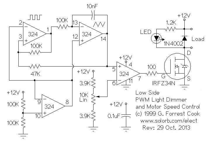
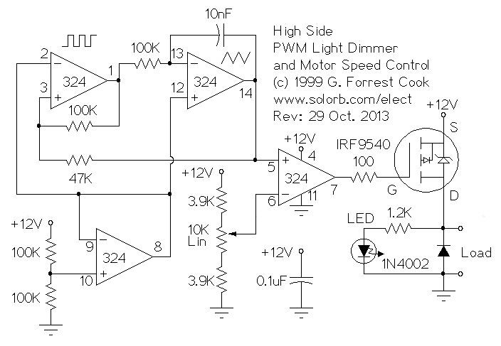
These two schematics are variations on another PWM circuit that I designed. The diagrams are for 12V operation only and there are high side (common ground) and low side (common +12V) versions. The low side version of the circuit uses an N Channel FET, the high side version of the circuit uses a P Channel FET. N Channel devices handle more current and cost less than P Channel devices. The high side version of the circuit is useful when one side of the load has to be grounded.
This circuit can switch a fairly high amount of current, an IRFZ34N MOSFET can handle over 35 Amps if connected to a proper heat sink. Higher power FETs, such as the IRFZ48N or IRF1010Z can be substituted if even larger currents are required. It is also possible to connect multiple FETs in parallel for even more current capacity. Always use thermally conductive grease between the FET and the heat sink, and remember that the heat sink is electrically live.
Inductive loads (motors) may require special care since they can generate large voltage spikes that can damage the MOSFET. Replacing the 1N4002 with a fast recovery diode may help absorb the reverse voltage kick when driving an inductive load such as a motor. If you use these circuits for experiments with electric vehicles, be sure to install a circuit breaker in series with the battery, the circuit breaker should be easy to reach by the driver. This is especially important due to the fact that when MOSFETs fail, they often short out, leaving the motor on at full speed.
Note that the pwm control has an opposite effect on these two circuits, the low side version is on with a high pin 7 output voltage and the high side version is on with a low output.
The 100 ohm resistor on the gate side of the power MOSFET transistor combines with the transistor's gate capacitance to form a low-pass filter. This slows down the MOSFET turn-on and turn-off slightly to reduce radio (RF) switching noise.
Note: if the circuit does not completely turn off and on when the 10K potentiometer is fully left and right, replace both of the 3.9K resistors with 3.3K resistors.
Back to FC's PWM Circuits page.