(C) 2026 G. Forrest Cook
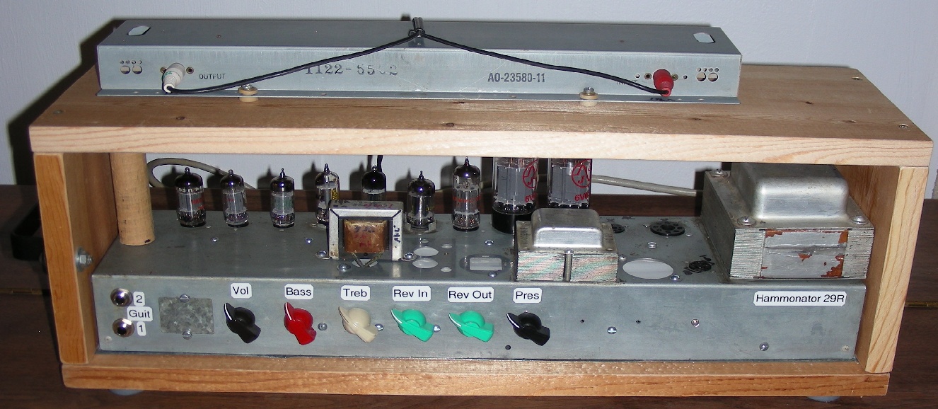
Hammonator 29R amp, click for a larger image.
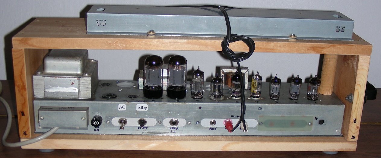
Hammonator 29R amp rear view, click for a larger image.
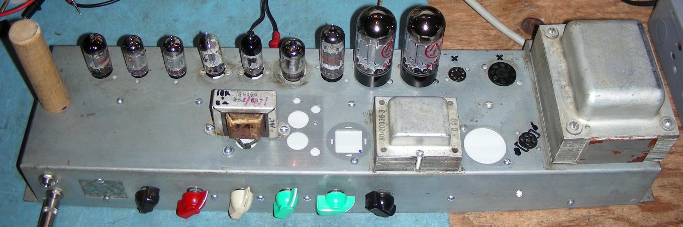
Hammonator 29R amp top view, click for a larger image.
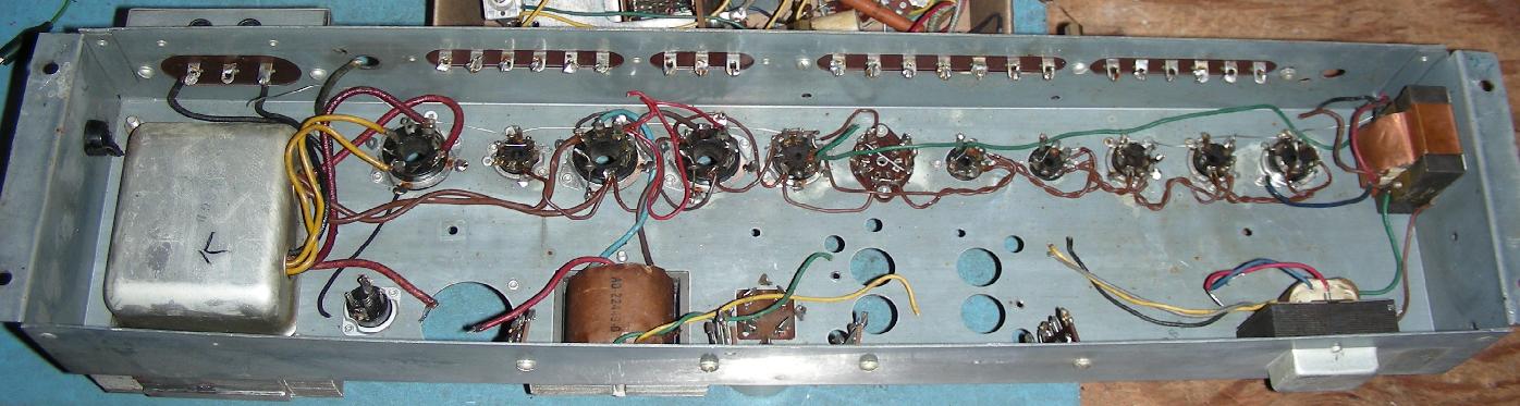
Stripped and cleaned Hammond AO-29-10 chassis, click for a larger image.
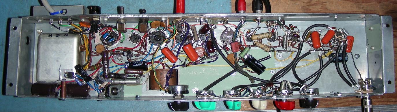
Hammonator 29R underside view, click for a larger image.
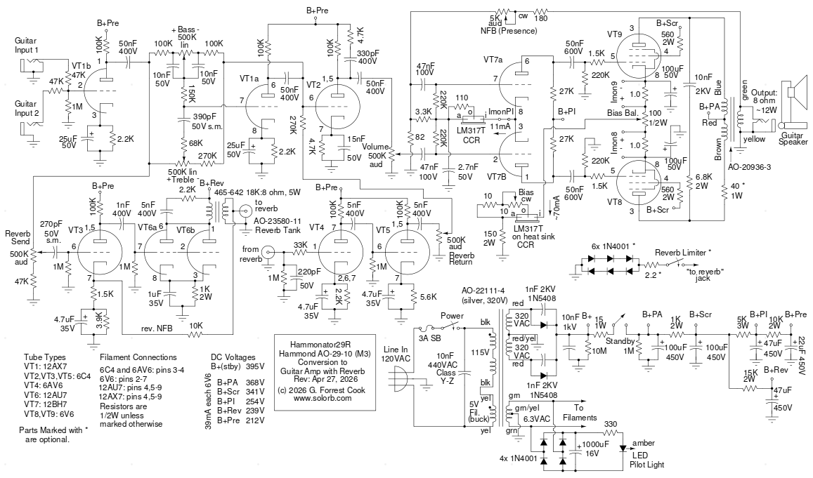
Schematic of the Hammonator 29R Hammond AO-29 amp conversion
The Hammonator 29R amp involves the conversion of a Hammond A0-29 M3 organ amplifier into a guitar amplifier with reverb. The amp produces around 12 watts of clean power into an 8 ohm speaker and has a very pronounced reverb effect. This is your author's tenth Hammond organ amp to guitar amp conversion project. It borrows a few circuit tricks from the Basserator bass amp conversion and the Spartacus Max guitar amp conversion. The Hammonator 29R has a similar layout and look as the Hammonator 2RVT guitar amp which is where it gets its name.
The Hammonator 29R has a number of interesting features. The tone stack is a modified version of a Max Robinson (Fun with Tubes) design and uses two triodes to provide true boost and cut action for the bass and treble controls. The reverb circuit is a new design that features both send (dwell) and return controls. The oversized reverb driver transformer along with a small amount of negative feedback in the reverb send amp produces a high quality drive signal to the reverb spring. A Hammond AO-23580-11 organ reverb tank with medium impedance send and receive coils gives the reverb channel a unique sound.
If the reverb send and return controls are set fairly high, the reverb can produce a small amount of tank feedback, which can enhance the reverb effect. There is also an optional but recommended reverb limiter circuit which can be switched in to limit the signals going to the reverb spring. This helps to protect the reverb transducer from bad sounding and potentially destructive overdrive and also produces a nice pre-reverb distortion effect at high reverb send levels while remaining inaudible at low send levels.
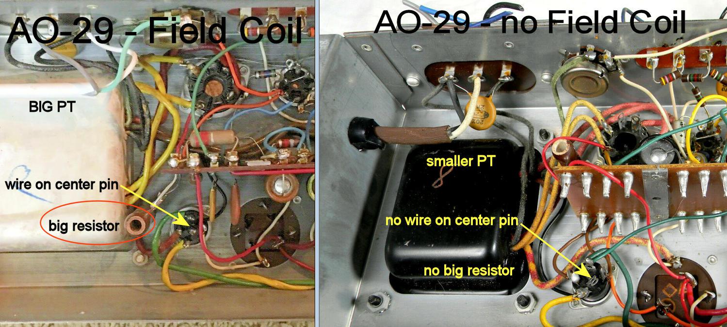
An important issue to consider before attempting to replicate this project is that there are quite a few versions of the AO-29 chassis, this amp was built on an AO-29-10 chassis. The main differences in the various AO-29 models involve the output voltage from the power transformer and whether the amp was used with a field coil speaker or a permanent magnet speaker. The field coil versions of the transformer have a higher output voltage (380V-380V) compared to the permanent magnet versions which produce (320V-320V). This amp uses the lower voltage transformer that was used with a permanent magnet speaker. There are also multiple versions of the 320V power transformers, this earlier AO-29 chassis used a large silver-colored transformer and the later versions used a smaller black transformer. Either of the 320V transformers should work with this circuit. The 380V transformer would be a better match if one were to modify the circuit for 6L6 output tubes.
Nine of the eleven tube sockets from the original amp were used in this design. Three 7 pin sockets were filled with 6C4 low gain triodes which are similar to half of a 12AU7. One 7 pin socket was filled with a 6AV6 high gain triode which is similar to half of a 12AX7. The 6AV6 was hand-selected for low microphonics, those tubes tend to be more microphonic than a typical 12AX7. Alternatively, a builder could remove several of the 7 pin sockets and widen the holes to accept 9 pin sockets with 12AU7 and 12AX7 tubes. Many different combinations of 7 and 9 pin triodes could be used with this circuit.
This is a fairly high-level project. It takes advanced technician skills to deconstruct and reconstruct the circuitry in guitar amplifiers. Also, there are plenty of lethal high voltages inside of this amp including 120 VAC, 395VDC and 640VAC. The project should only be taken on by someone who has experience working with high voltage circuitry. The power cord should always be unplugged when working on the amp. The circuitry will eventually discharge the capacitors when power is turned off, but it is always a good idea to short out the electrolytic capacitors before working on the amp.
The first job to do when converting an old organ chassis is to use a metal file to smooth out the sharp metal corners and edges on the bottom of the box. This will prevent you from cutting your fingers as you work on the amp. Clip off most of the components and wires that connect between the tube sockets and the two parts boards. Be very careful not to damage the tube socket pins. Leave all of the original wiring on the rectifier socket and all of the brown filament wires. De-solder the remaining wire segments from the tube socket pins, a Soldapullt tool, an Xacto knife and diagonal cutters can be used. This process takes a lot of time and patience, take your time and take breaks. Always do soldering work in a well ventilated area.
The volume control tower was removed, this can optionally be used as a dog house for the electrolytic capacitors, mine was missing the side cover so it was no longer of any use. The two large bakelite tag strips were removed from the back of the chassis by drilling out the rivets. The three interstage and percussion transformers were removed from the chassis. The two original electrolytic capacitor cans were removed from the chassis. Metal cover plates were cut out and drilled so that they could be screwed to the chassis to cover the holes left from the removed components. Numerous 6-32 screws and nuts were used to attach the new cover plates, these can also be used to secure the new tag strips.
After the tube socket pins were cleared, a dental tool was used to scrape off the solder flux residue from around the pins. All of the left-over solder bits were scraped off of the chassis and were removed with a vacuum. The top of the chassis and the two remaining transformers should be cleaned with a mild detergent and a wire brush. Be sure to preserve the inked part numbers on the transformers.
The AO-29 chassis includes many small ground wires that connect between the terminal strip ground tags and the tube socket edge tags. These wires improve the overall ground system and insure that it does not rely on the old socket rivets which can become oxidized over time. Many new ground wires were added between the main ground bus and the ground lugs of the newly added terminal strips. Use thicker gauge wiring between the power transformer's high voltage center tap and the electrolytic filter capacitor bank. The power cord ground lead should have a connection to the common bus.
The crusty old AC power cord and its cable clamp were removed from the side of the chassis. A new a three-wire power cord was installed in the small metal box on the back of the amp and was secured to the box with a zip-tie. The power cord was soldered to the three tags. A hole was drilled in the back of the chassis for the fuse holder.
Holes for the controls, jacks, switches, fuse and pilot light were marked, punched, drilled and filed smooth. It is recommended that most of the metal work is completed before wiring in the new components. A 3-3/4" long piece of 1" wooden dowel was cut, drilled and screwed to the top of the chassis, this allows the bottom of the amp to be worked on without damaging the fragile and expensive tubes.
The two 1N5408 diodes and associated capacitors were wired across the back of the 5U4 socket. The new wiring was mostly done with solid copper wire that was removed from the original amp wiring. The various B+ lines were run with differently colored wires to make it easy to trace the different circuits. Much of the signal wiring was done with audio-grade coaxial wire, it is generally a good idea to only connect the coax shield to ground on one side of the cable to eliminate ground loops.
A simple cabinet can be built from 3/4" pine boards, examples can be seen on some of my other Hammond amp conversion pages. The top and bottom boards can be cut to 22-1/4" long by 7" wide. The sides can be cut to around 7" tall by 7" wide, they should allow for at least 1/2" of clearance to the top of the power tubes. A bottom shield plate made from sheet metal can be cut to fit under the amp. The plate should be exactly as wide and slightly deeper than the chassis to provide some overlap on the chassis edges. Holes should be drilled in the bottom plate so they align with the four holes in the chassis. The bottom shield plate should be glued to the lower cabinet board using construction adhesive, this will prevent mechanical vibrations from occurring.
The top and bottom pieces should be pre-drilled and the top holes should be countersunk. The top and bottom pieces can then be screwed into the two side pieces using eight wood screws. Four rubber feet can be attached to the bottom mounting holes using the same screws. A heavy-duty carrying handle should be added to the side board, opposite from the power transformer. It is recommended that a tube protector grille should be added to the back of the amp to keep fingers away from the tubes. A good grille material is 1/4" grid wire cloth.
The reverb tank can be screwed onto the top of the cabinet. The tank should be oriented with the jacks toward the rear of the amp and as far to the left as possible to avoid picking up hum from the power transformer. The Hammond reverb tanks were designed to be operated on their side with the jacks facing up, your author has never had a problem running them with the open side facing down. If the amp were mounted in a speaker cabinet, vertial mounting would be possible. Fender amps use a sound-proofing bag around their reverb tanks when they are mounted near speakers, that would be a good addition if you make a combo amp and speaker in the same cabinet.
The AO-29-10 power supply uses a large AO-22111-4 power transformer that was intended to be powered from a nominal 117V line voltage. The 5VAC filament winding that was originally used for the rectifier tube filament was re-wired as a buck winding in series with the 117VAC primary winding. This reduces the transformer's output voltages and adapts the transformer to the modern 120VAC line voltage. Be sure to get the phasing of the 5V winding correct by checking the voltage on the 6.3VAC filament winding before and after adding the buck, it should be lower with the buck winding connected and close to 6.3VAC.
The high voltage supply is rectified with two 1N5408 diodes, spike-filtered with a 10nF capacitor, surge limited with a 15 ohm resistor and switched on and off by a Standby switch. The high voltages are lowered with series resistors and further filtered by additional capacitors in order to supply the 6V6 screen grids, phase inverter, reverb output and preamp stages. The series resistors have oversized wattage ratings to insure long life. The capacitors before and after the standby switch have high value bleeder resistors to discharge them when the power is shut off.
The power amp section consists of a pair of JJ brand 6V6 beam-power tubes feeding the Hammond AO-20936-3 output transformer. The 6V6 screen grids are supplied through a pair of 470 ohm grid-stopper resistors and the 6V6 control grids have similar 1.5K grid-stopper resistors. The grid-stoppers help to tame the tubes by lowering their response to radio frequencies on the control grids and eliminate negative resistance effects from the screen grids. A pair of one ohm resistors were installed between the 6V6 cathodes and the cathode current regulator for monitoring the cathode currents. Four pins on the 5 pin round connector (formerly the speaker output) that is located near the power transformer are used for bias current monitoring.
The output tube plates drive the output transformer and the RC snubber across the transformer helps to dissipate high frequency signals that can cause damaging high voltage spikes in the output transformer primary. An optional 40 ohm resistor in series with the brown output transformer lead equalizes the DC coil resistance with the blue lead for better balance.
The PA Presence (Gain) control acts as a variable negative feedback circuit by feeding the speaker output back to the phase inverter input. The yellow output transformer secondary wire connects to ground and the green wire connects to the speaker output and NFB circuit. If the Presence control causes an oscillation when it is at its lowest resistance setting, swap the two output transformer speaker leads.
The phase inverter uses a 12BH7 dual-triode in a current-mirror long tailed pair circuit. An LM317 adjustable voltage regulator is wired as a constant-current source for the two 12BH7 cathodes. The constant-current circuit improves on similar phase inverter designs by insuring that triodes are run at the same idle current and gain. The master Volume control feeds one side of the phase inverter and the Presence control feeds the negative feedback signal to the other side.
The input preamp uses a fairly basic Fender-style circuit, there are two 47K grid-stopper resistor which lower the response to high frequency (RF) signals. The dual input jacks are wired so that Input 1 is high gain and Input 2 is across the Input 1 47K resistor to ground for lower gain. Both inputs become high gain if they are used at the same time. The 1M resistor on the grid acts as a grid-leak to provide a ground reference for the 12AX7 grid. The cathode RC circuit is a standard high-pass design, the 2.2K resistor sets the operating current and the 25uF in parallel with this resistor sets the low frequency roll-off for this stage.. The 5nF plate capacitor was selected for the best bass/treble balance, this value can be adjusted if you want more or less bass response from the amp, values between 5nF and 20nF should work.
The tone control circuit is based on a design that was found on an earlier version Max Robinson's Fun With Tubes site. The tone control uses an active negative feedback circuit to produce a wider range of buck and boost control compared to passive tone control circuits. The tone stack was modified in several ways to make it have a response that is useful for a guitar amp. An R-C network with a 560K resistor and 200pF capacitor was added to level out the high frequency response and the padder resistors on the tone controls were modified for improved response at the max and min control settings. The amp's response is close to flat when the bass and treble controls are centered. The active tone control is followed by a 12AU7 gain-recovery stage (VT2).
The reverb send circuit taps its signal off of the VT1b preamp tube and feeds the Reverb Send pot. The 47K resistor on the lower end of the Reverb Send pot insures that a minimal amount of signal will always be sent to the reverb. The VT3 triode boosts the clean reverb send signal. The boosted signal is sent to the parallel-wired triodes of VT6, which powers the reverb driver transformer and the reverb tank. All of the coupling and cathode capacitors in the reverb channel were chosen to pass higher frequencies and attenuate lower frequencies.
The R/C snubber across the reverb driver transformer primary attenuates the highest frequencies and reduces distortion in the reverb tank. The 10K NFB resistor in conjunction with the 1.5K cathode resistor on VT3 provides a small amount of negative feedback, this stabilizes the reverb send signal, improves the fidelity and reduces unwanted voltage spikes.
the Reverb Send signal was temporarily monitored with a small speaker that was connected to the reverb send line. An 8 ohm speaker has a lower impedance than the AO23580-11 reverb tank input coil, a 16 ohm or 32 ohm speaker would be better for testing purposes. The reverb output transformer was selected out of a batch of used single-ended output transformers until the best sounding output was found. The transformer I used has an impedance ratio of 18K to 8 ohms, both values go up when connected to the medium input impedance of the AO23580-11 reverb tank. If an 18K:8 transformer cannot be found, a 20K:8 unit should perform similarly. If a lower input impedance tank such as the AO23580-10 is used, a different transformer impedance ratio would be required.
The reverb return circuit uses two stages of amplification, VT4 and VT5 boost the signal up to a level that is suitable for mixing with the the tone control circuit. The 220pF capacitor on the input of the reverb return prevents oscillation when the reverb cable is disconnected. The 33K grid stopper resistor on VT4 reduces the sensitivity of the tube to RF interference that may be picked up by the input wire. The output of the reverb return control is routed to the grid of VT2 in the tone stack circuit via a 270K gain reduction resistor. If the Reverb Send and Return controls are both turned up to near maximum, a small amount of the return signal can couple back through the tone stack into the reverb send circuit, this feedback can enhance the reverb effect.
Alignment of the amp should be performed whenever a different set of 6V6 tubes are installed. Measure the idle current of the two 6V6 tubes by inserting DVM probes into the approriate pin pairs on the 5 pin round socket next to the power transformer. The DVM should be set to measure volts and the current is the same as the voltage shown. Adjust the idle current with the 10 ohm variable resistor on the LM317T regulator IC and balance the currents of the two tubes using the 100 ohm Bias Balance pot. The two controls interact, so repeat both adjustments until you have matched readings at the appropriate current.
The idle current should be somewhere between 30mA (0.03V) and 45mA (0.045V). Higher values will produce more output power and less cross-over distortion while lower values will allow the tubes to run cooler and last longer. A 35mA idle current is a good value to start with if using new tubes. If you are using antique 6V6 tubes, it may be better to use a lower bias current to maximize tube life.
Set the idle current of both tubes to the same value by adjusting the two bias controls and monitoring the two current test points. There will be a small amount of interaction between the controls. Either bias control should be tweaked a small amount to achieve the minimum speaker hum level when the amp is idle. Adjust the filament hum balance control for the minimum hum in the speaker, this should be near the center of its range. That completes the alignment of the amp.
The Hammonator 29R is a medium power, clean-sounding amp with very good fidelity and a broad range of tone control. It works very nicely with most electric guitars. A 10 or 12 inch, 8 ohm guitar speaker is a good fit for this amp.
Start with the standby and power switches turned off. Turn on the power switch. Wait at least 30 seconds for the tube filaments and cathodes to warm up then turn the standby switch on. Set the Presence control to its mid range, lower levels are good for a clean and tight sound while higher levels are good for a punchy loud sound. I like to adjust the presence control just above the point where the sound level begins to drop. Plug in your guitar, turn the volume up to a comfortable level and adjust the tone controls for the desired tone. Play your instrument and enjoy the warm tube sound.
The Reverb Send and Return controls work together to change the character and loudness of the reverb effect. Typically you can increase one control and decrease the other to get a reverb sound that you like.
To power the amp down, turn off both the power and standby switches. If you want to take a short break, leave the power on and turn the standby switch off. The tubes will last longer if you don't leave them powered on for extended periods, especially with the standby switch turned on. If you are working on the amp, leave the standby switch on and turn off the power switch, this will cause the high voltages to drop more quickly.
This amp can be built without the reverb effect which can be a good way to get an amp up and running quickly. The reverb circuitry can be added later. The non-reverb version of the amp should have a 470K resistor to ground on the tone contol input where the 100K bass control resistor connects to the 500K treble control. The 470K resistor should be removed if the reverb circuit is built later. The 10K resistor between the B+PI and B+Pre should be changed to 15K to lower the preamp B+ voltage until the reverb circuitry is added..
The cathode circuit on the output tubes could be replaced with a simpler cathode bias circuit, at the expense of easy cathode current adjustability. The 6V6 cathodes would need to be tied together and connected to ground via a parallel resistor and capacitor. The resistor value should be set to give the desired cathode current.
If the AO-29 chassis has a 380-380 Volt power transformer, the output tubes could be changed to 6L6 or 5881 tubes for higer power output. The circuit would need higher value power supply dropping resistors to achieve the correct voltages for the phase inverter and reverb supplies. The power tube bias adjustment would also need to be adjusted to a higher level to support the bigger tubes.
Back to FC's Music Circuits page.